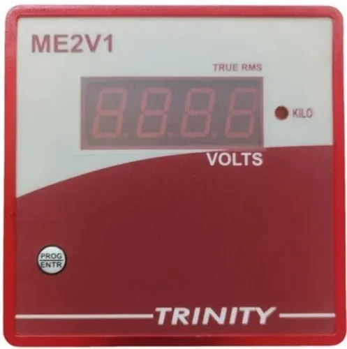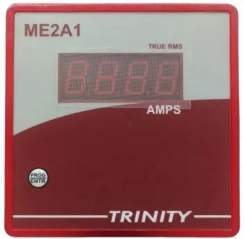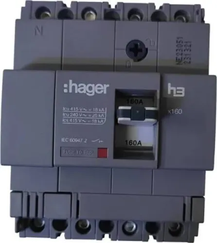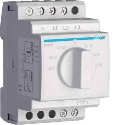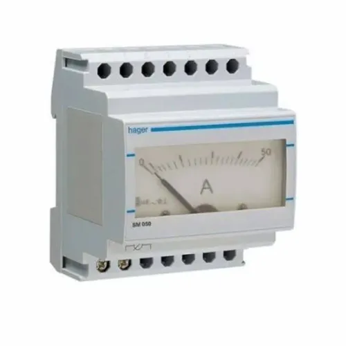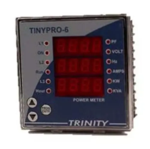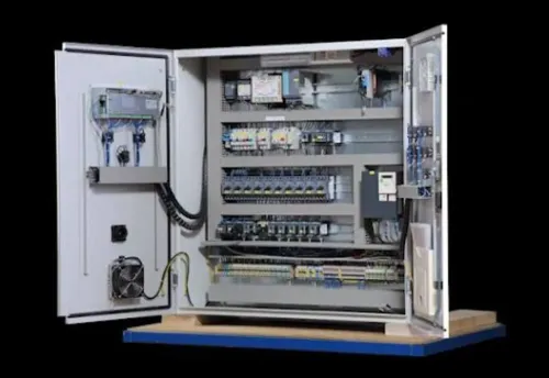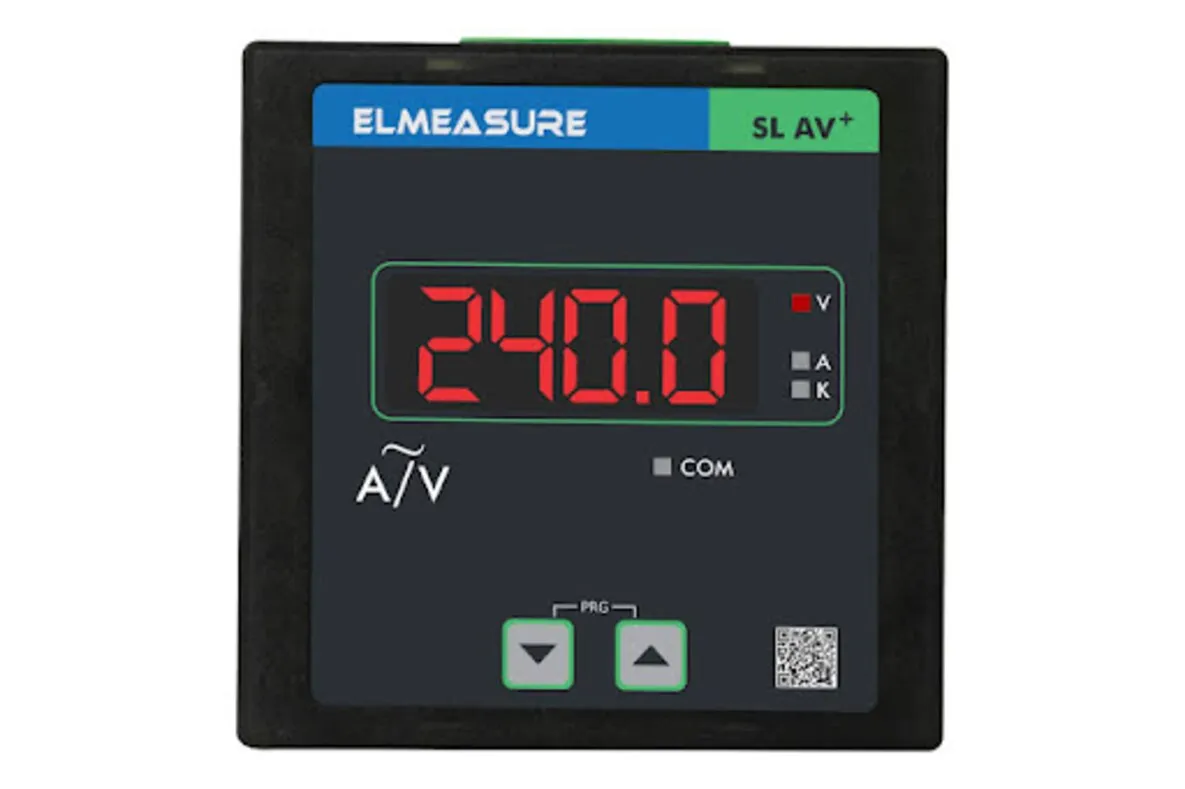
Choosing between a dedicated ammeter, a VAF meter and a multifunction instrument depends on the panel’s wiring, CT circuit, auxiliary supply, measurement needs and available space—not on the display range alone. By the end, you will have a practical specification for ME2A3 ammeter selection, a commissioning checklist and a supplier-comparison method for a Nagpur plant retrofit or new panel.
Key takeaways
- Confirm whether the feeder is 3-phase, 3-wire or 3-phase, 4-wire.
- Match CT ratio, secondary current and burden to the ammeter input.
- Check accuracy, auxiliary supply, panel cutout and display before ordering.
- Never open a live CT secondary; short it before disconnecting the meter.
Start with the feeder, wiring system and job the display must perform
Choose the meter from the feeder’s wiring system and the decision you need to make at the panel. Specify whether the circuit is 3-phase, 4-wire or 3-phase, 3-wire before selecting an industrial three-phase panel ammeter.
| Meter type | What it displays | When it fits |
|---|---|---|
| Dedicated three-phase ammeter | Phase currents, either simultaneously or one selected phase at a time | You need feeder loading and phase-balance checks |
| VAF meter | Voltage, amperes and frequency | Operators need basic electrical values in one instrument |
| Multifunction meter | Current, voltage, frequency, power, energy, power factor and related values | You need operating records, alarms or energy analysis |
A 3-phase, 3-wire instrument generally measures the three line currents but does not show neutral current. Choose a 4-wire model, or confirm a separate neutral input or fourth current channel, when neutral loading matters.
Do not assume an ME2A3 ammeter shows L1, L2 and L3 simultaneously. During ME2A3 ammeter selection, check the exact datasheet for phase indication, display sequence, number of current inputs, 1 A or 5 A CT input, true-RMS measurement, auxiliary supply, overload withstand, scaling and panel cut-out.
The meter reads a CT circuit, not a 0–5000 A feeder directly. Measurement quality depends on the CT class, burden, lead resistance, configured ratio and meter accuracy; an expensive meter cannot correct an overloaded CT.
Confirm the instrument’s current inputs are isolated from each other and from the auxiliary supply before wiring phases from separate CTs.
Match the CT circuit to the meter instead of the other way around
A 600/5 A CT sends 5 A to the ammeter when the feeder carries 600 A. Set the meter to a 600:5 ratio; configuring it as 5:5 will produce a severely wrong display, not a small accuracy error.
Select the CT primary rating above the feeder’s maximum expected current while keeping normal load near the CT’s useful measuring range. Include CT class, rated burden, lead resistance and meter accuracy in the calculation.
| CT secondary | Meter input | Practical choice |
|---|---|---|
| 1 A | 1 A | Long panel runs or lower lead losses |
| 5 A | 5 A | Common retrofit and short control wiring |
| 1 A | 5 A, or 5 A | Incompatible without a matching transducer |
During ME2A3 ammeter selection, ask a three phase ammeter supplier to confirm these points in the datasheet, not from the model code alone:
- The exact CT input: 1 A or 5 A, three current channels, terminal arrangement and programmable primary ratio.
- The system connection: 3-phase, 3-wire or 3-phase, 4-wire. Confirm whether it shows L1, L2 and L3 separately or only one selected phase.
- The CT burden, accuracy class and lead resistance. The meter’s input burden plus wiring must stay within the CT’s rated VA.
- Auxiliary supply separately from the measured circuit: 230 V AC, 110 V AC, 24 V AC/DC or the specified wide range.
- CT polarity, overload withstand and true-RMS capability where distorted drives or rectifiers are present. Never open an energised CT secondary.
Specify measurement quality, supply and panel-fit details before ordering
A meter that fits the panel cut-out can still give unreliable readings if its auxiliary supply, wiring system, isolation, or measuring chain is wrong. State whether the installation is 3-phase, 3-wire or 3-phase, 4-wire, then specify the panel supply separately from the measured current circuit.
A 230 V AC meter is not interchangeable with a 24 V AC/DC control-panel instrument.
| Specification | Confirm before ordering | Failure if missed |
|---|---|---|
| Electrical system | 3-phase, 3-wire or 3-phase, 4-wire; three line-current inputs and neutral indication if required | A 3-wire unit will not show neutral current without a separate neutral input or fourth channel |
| Auxiliary supply | 230 V AC, 110 V AC, 24 V AC/DC, or the stated wide-range rating | The display will remain dead or suffer damage |
| Input isolation | Isolation between current inputs and between inputs and auxiliary supply | CTs on separate phases can create an incorrect wiring scheme or unsafe potential |
| Measurement quality | CT class, burden, lead resistance, programmed ratio, meter accuracy, and 1 A or 5 A secondary input | An accurate meter still gives inaccurate current when the CT is overloaded or mismatched |
| Display behaviour | Refresh rate or averaging time | Slow averaging can hide motor-starting overloads |
| Environment and fit | Operating temperature, humidity, enclosure conditions, cut-out, depth, terminal clearance, and mounting method | Heat, condensation, or insufficient rear clearance causes failure or rewiring |
Ask a digital ammeter supplier to document these values, not just quote a model number. Also identify the MCCB, overload relay, electronic trip unit, or motor-protection relay responsible for protection; an industrial three-phase panel ammeter displays current but does not automatically provide overload, short-circuit, earth-fault, or phase-loss protection.
Commission the meter without creating a CT or diagnosis problem
Confirm the panel is dead, identify L1, L2 and L3, and check that the wiring matches a 3-phase, 3-wire or 3-phase, 4-wire system. Connect each CT secondary to the matching current input, observe polarity, and never leave an energised CT secondary open. Use a shorting link before disconnecting any meter wire.
- Verify the auxiliary supply separately from the measured circuit: 230 V AC, 110 V AC, 24 V AC/DC, or the specified wide-range input. A 230 V-only meter will fail in a 24 V control circuit.
- Check whether the current inputs are isolated from each other and from the auxiliary supply. Add isolation or change the wiring scheme when the manual requires it.
- Confirm every CT secondary is 1 A or 5 A as programmed, enter the CT ratio, and tighten terminals to the manufacturer’s torque.
- Energise the auxiliary supply first, then the feeder. Compare each displayed phase with a clamp meter under a stable load; reversed polarity produces a negative or implausibly low reading.
- Confirm the meter identifies L1, L2 and L3 correctly and does not promise neutral current on a three-wire model without a neutral input or fourth channel.
- Record the display refresh or averaging time before investigating motor-starting complaints.
A three phase ammeter supplier should provide the wiring diagram and commissioning limits. Ask the digital ammeter supplier three phase in Nagpur for the test procedure, isolation details and fault codes. Treat the display as indication, not protection: MCCB, overload relay, electronic trip unit or motor-protection relay must handle trips.
After any cut-out modification, recheck clearances, segregation, temperature-rise assumptions and routine verification under IEC 61439.
Compare Nagpur suppliers by documentation and retrofit support
Put the auxiliary supply, wiring system, CT input and display behaviour in the purchase order, not just “three-phase ammeter.” Your brief to a digital ammeter supplier three phase in Nagpur should distinguish the measured circuit from the meter supply.
| Requirement | Put in the purchase order | Proof before approval |
|---|---|---|
| System | 3-phase, 3-wire or 3-phase, 4-wire; state whether neutral current is required | Wiring diagram showing L1, L2, L3 and neutral inputs, if fitted |
| Auxiliary supply | 230 V AC, 110 V AC, 24 V AC/DC or the specified wide-range supply | Datasheet and terminal diagram; a 230 V-only meter is not a substitute for a 24 V control-panel model |
| CT input | 1 A or 5 A secondary, CT ratio, polarity, burden and terminals | Supplier demonstrates that a 600/5 A CT is configured as 600/5, not 5/5 |
| Signal design | Input isolation between phases and from auxiliary supply | Internal specification or wiring proof showing whether external isolation is needed |
| Display behaviour | Refresh rate or averaging, especially for motor starting | Demonstration showing whether brief overloads appear or disappear in averaging |
Before approval, ask the digital ammeter supplier for the signed datasheet, GA drawing, terminal schedule, CT wiring diagram and calibration or test record. Reject any quotation that omits CT-secondary shorting instructions: short the CT before disconnecting an energized meter.
Whether you use Contact Electrical & Automation Pvt Ltd or another vendor, require a panel-fit check against the existing cut-out, terminal access and control voltage before release.
Related products
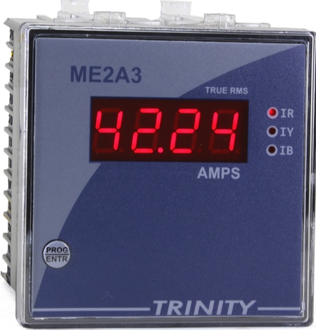 | THREE PHASE AMMETER (ME2A3) Amps (0-5000A AC) of three phase on 0.56" seven segment LED View product → |
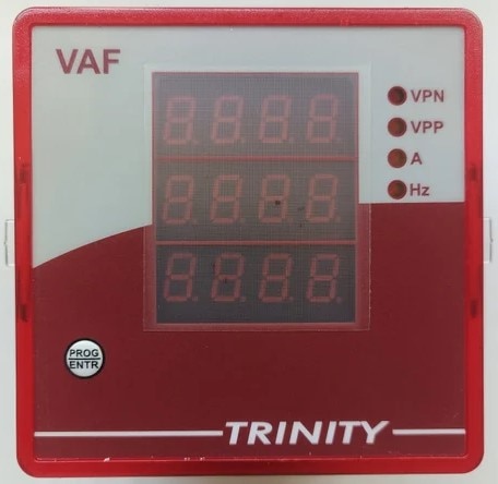 | DIGITAL PANEL METER, MODEL:VAF DIGITAL PANEL METER, MODEL:VAF A VAF meter (Voltage, Amperage, Frequency) is a digital panel-mounted instrument used to measure, monitor, and display key electrical parameters in... View product → |
Frequently asked questions
How do I choose an industrial three-phase panel ammeter?
Start with the feeder wiring system and the panel task. Confirm whether the circuit is 3-phase, 3-wire or 3-phase, 4-wire, then specify the readings, CT inputs, auxiliary supply, accuracy and panel cutout.
Why must the CT circuit match the ammeter?
The meter input must suit the CT secondary rating, commonly 1 A or 5 A, along with the CT ratio, burden and wiring arrangement. A mismatch produces incorrect readings and can create a hazardous open-CT condition.
What should I check before ordering a ME2A3 ammeter?
Confirm the exact measurement configuration, CT input, auxiliary voltage, accuracy class, display range, terminal layout, panel cutout and required communication or alarm functions. Use the manufacturer’s datasheet rather than the model name alone.
How should I commission a three-phase ammeter safely?
Isolate the panel, verify the CT wiring and polarity, and short the CT secondary before disconnecting any meter connection. After energising, compare phase readings with a trusted clamp meter and investigate reversed or implausible values.
How can I compare a digital ammeter supplier in Nagpur?
Ask each digital ammeter supplier for the datasheet, wiring diagram, CT compatibility details, accuracy information, supply range, cutout dimensions and commissioning support. For a retrofit, also confirm terminal access, replacement compatibility and troubleshooting help.
Related product
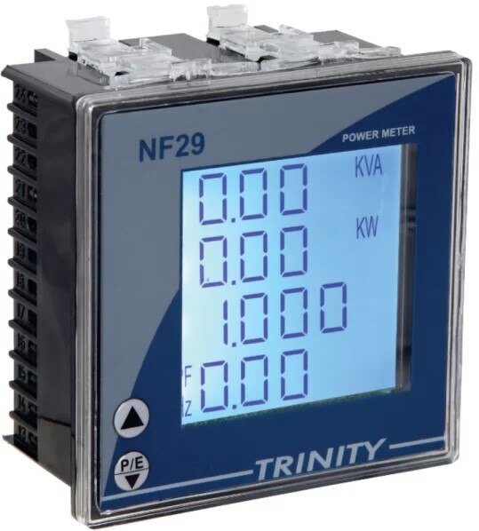 | MULTIFUCTION PANEL METER MODEL: NF29 MULTIFUCTION PANEL METER MODEL: NF29 MFM With Customized LCD, With THD View product → |
Keywords