A digital ammeter that fits the panel can still deliver wrong readings if its input method, CT arrangement, accuracy basis or system topology is mismatched. Use the checks below to compare suppliers on electrical compatibility, evidence, installation risk, commissioning effort and support before you issue a purchase order.
Key takeaways
- Confirm AC or DC, phase configuration, frequency and current-transformer ratio first.
- Do not treat the displayed range as proof of accuracy across the full range.
- Request overload ratings, terminal clearances, cutout dimensions and calibration records.
- Verify standards evidence, communication protocols, warranty terms and technical support before ordering.
Start with the panel’s electrical system and sensing method
Before a digital ammeter supplier recommends a model, confirm the panel topology and sensing method: AC or DC measurement, system frequency, line-to-line or line-to-neutral voltage, and the required current range. Specify single-phase, three-phase three-wire, or three-phase four-wire operation, including whether the load is balanced or unbalanced.
If a specification uses the phrase “three-phase three-wire systemomology?”, ask the supplier to define it.
| Panel condition | Supplier must confirm | Risk if mismatched |
|---|---|---|
| Single-phase | Direct input or one CT, voltage reference and polarity | Wrong phase or voltage reference produces false readings |
| Three-phase three-wire | Independent CT inputs, required voltage connections and calculation method | A four-wire meter can misread without the required reference |
| Three-phase four-wire | Neutral availability, neutral measurement and phase-to-neutral sensing | Unbalanced-load current can be reported incorrectly |
Ask whether the instrument is only an indicating ammeter or a power-monitoring device. IEC 61557-12 addresses power metering and monitoring devices in low-voltage distribution systems; it does not automatically cover a simple current display.
For CT-operated measurement, confirm 1 A or 5 A secondary rating, CT ratio programming, allowable input range, burden in VA or ohms, polarity, and a CT shorting terminal or test block. Never rely on removing the meter from an energized CT circuit: an open secondary can generate dangerous voltage.
Finally, match input isolation and CAT III or CAT IV rating to the actual terminals and transient environment. Require accuracy for the complete chain, including CT class, phase-angle error, cable length, terminal resistance, and any summing or interposing CTs.
Separate a displayed current range from real measurement capability
An advertised 0–5000 A range describes display scaling, not proof that the meter measures 5000 A directly. Ask whether the input is direct or supplied through a current transformer, then confirm the programmed CT ratio, scaling resolution and overload withstand rating.
A meter showing 5000 A may actually accept only a 1 A or 5 A secondary signal.
Require the supplier to state:
- Whether accuracy is expressed as a percentage of reading, percentage of range or percentage of full scale
- Whether the quoted error includes the current transformer, cable resistance, terminal resistance, temperature drift and display resolution
- The allowable input range and burden in VA or ohms for the specified CT
- Compatibility with a 1 A CT secondary rating, rather than assuming a meter designed for 5 A CT inputs will work
- The accuracy class and phase-angle error of the CT, plus the effect of its CT ratio and cable length
A ±1% full-scale specification on a 0–5000 A display permits roughly ±50 A error throughout the stated scale, even at a low operating current. That reading becomes less useful when the complete measuring chain adds CT and wiring error.
Confirm whether the meter measures each CT independently or calculates a sum, and match it to the actual single-phase, three-phase three-wire or three-phase four-wire arrangement. For drives and nonlinear loads, request bandwidth, crest-factor, frequency and accuracy data for distorted waveforms; “true RMS” alone proves little.
Check safety, overload performance and panel installation requirements
Reject any supplier who cannot provide a datasheet for the meter at the installed point, not merely its nominal voltage. Ask for these proofs before releasing the panel drawing:
1. Confirm input isolation, terminal-to-terminal voltage limits, and the overvoltage category at the measurement terminals. A CAT III rating is not interchangeable with CAT IV at the same nominal voltage; the category must match the panel’s connection point and transient exposure.
2. Require separate continuous overload and short-duration withstand ratings. “Overload protection” might describe only a brief test pulse or an internal fuse. For CT measurement, obtain the supported secondary rating—1 A or 5 A—input burden in VA or ohms, allowable range, and CT ratio scaling. The total burden includes cable resistance and the meter input.
3. Obtain the panel cutout dimensions, mounting depth, terminal clearance, conductor size, and rear ventilation requirements. Confirm operating and storage temperature, humidity, altitude, vibration, and condensation limits. A front-panel IP rating under IEC 60529 does not protect rear terminals or the complete enclosure.
An energized CT circuit also needs a specified shorting method, such as CT shorting terminals or a test block, before meter removal. An open CT secondary can generate dangerous voltage.
Finally, identify whether the device only indicates current or qualifies as a power-monitoring device; IEC 61557-12 addresses low-voltage power metering and monitoring devices, not every simple panel ammeter.
Demand evidence for standards, calibration and communications
A CE mark is not an immunity test. Request the Declaration of Conformity, the exact IEC 61326-1 classification, and the test environment used. A meter tested for a controlled laboratory environment is not automatically suitable beside contactors, variable-frequency drives, and switching transients in an industrial panel.
Ask for these records before approving the model:
- An IEC 61010 safety test report covering the stated supply, measurement terminals, installation category, and pollution degree.
- Evidence for IEC 61557-12 when the device measures power quantities in a low-voltage distribution system. A simple indicating ammeter may fall outside that standard; the supplier must state why.
- A calibration certificate listing test points, readings, correction values, and measurement uncertainty. Prefer traceability through an ISO/IEC 17025 laboratory; a pass/fail factory sheet is not equivalent.
- Separate continuous-overload and short-duration withstand ratings for the direct input or CT input. “Overload protection” alone proves little.
- The IEC 60529 IP rating and environmental test limits for the complete installed arrangement. A front-panel rating does not protect rear terminals or ventilation openings.
- For communications, request the protocol name, register map, scaling rules, baud and parity settings, supported function codes, and a test record showing the displayed value reached the control system.
| Evidence | What it verifies | Reject when |
|---|---|---|
| IEC test report | Safety and EMC performance | It names a different model or environment |
| Calibration certificate | Measurement traceability and uncertainty | It gives only pass/fail |
| Communication test record | Reliable data transfer | It shows no register values or scaling |
For North American panels, also demand the exact UL or CSA certification scope, including model, voltage, terminals, and mounting conditions.
Use a supplier due-diligence checklist before placing the order
Before placing the order, use the same supplier comparison checklist for every quote. Compare evidence, not catalogue claims: request drawings, protocols, delivery dates, site assistance and the name of the person who will resolve faults.
| Area | Ask for | Reject the quote if |
|---|---|---|
| Documentation | Wiring diagram, CT ratio and secondary rating, burden, overload rating, environmental limits, and an ISO/IEC 17025 calibration certificate with traceability and measurement uncertainty | You receive only a pass/fail factory test sheet |
| Communications | Modbus register mapping showing scaling, signed or unsigned values, phase mapping, update rate, byte order, address, timeout and communication-loss behaviour | The supplier confirms only “Modbus available” |
| Delivery | Written lead time, inspection point, packing method, spare-unit availability and notification of substitutions | The date is verbal or depends on unspecified stock |
| Commissioning | Commissioning support, parameter settings, CT polarity checks and a test procedure for local and remote readings | Your team must discover programming and wiring requirements on site |
| After-sales | Named technical contact, response time, warranty exclusions, firmware policy and replacement process | Support ends with dispatch |
For an offer from Contact Electrical & Automation Pvt Ltd, apply these same checks to the proposed ammeter and panel interface rather than accepting a familiar supplier name as proof.
Disqualify any quote that omits a CT-secondary shorting method for an energized circuit, or refuses to state accuracy under distorted waveforms and the installed temperature, humidity and altitude.
Related products
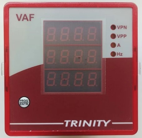 | DIGITAL PANEL METER, MODEL:VAF DIGITAL PANEL METER, MODEL:VAF A VAF meter (Voltage, Amperage, Frequency) is a digital panel-mounted instrument used to measure, monitor, and display key electrical parameters in... View product → |
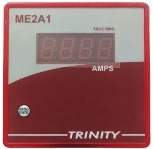
 | SINGLE PHASE AMMETER (ME2A1) AMPS (0-5000A AC) Of One phase on 0.56" seven segment LED View product → |
Frequently asked questions
What electrical details should you give a digital ammeter supplier?
Provide AC or DC measurement, system frequency, line-to-line or line-to-neutral voltage, current range, phase arrangement, load balance and current-transformer ratio.
How can you distinguish a displayed range from real measurement capability?
Check the accuracy class, stated measurement range, starting current, resolution, input burden and performance across the operating range rather than relying on the display limit.
What safety and installation checks matter for panel ammeters?
Review continuous and short-duration overload ratings, insulation and impulse withstand ratings, terminal clearances, enclosure requirements, panel cutout dimensions and wiring access.
What evidence should a supplier provide before you place an order?
Request the datasheet, installation manual, test or calibration record, applicable standard references, communication details, warranty terms and a completed technical offer.
Related products
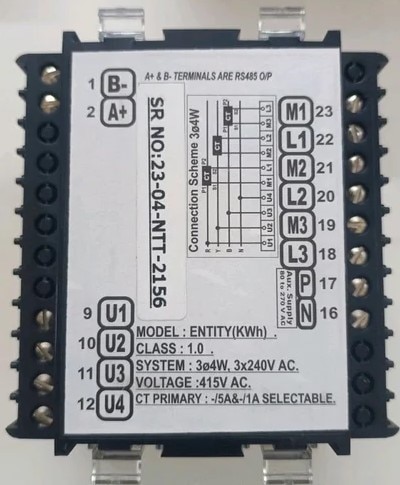 | Digital Energy Meter MODEL: Entity KWH Digital Energy Meter MODEL: Entity KWH ENTITY KWH, KVARH, 60 Amp with RS485 View product → |
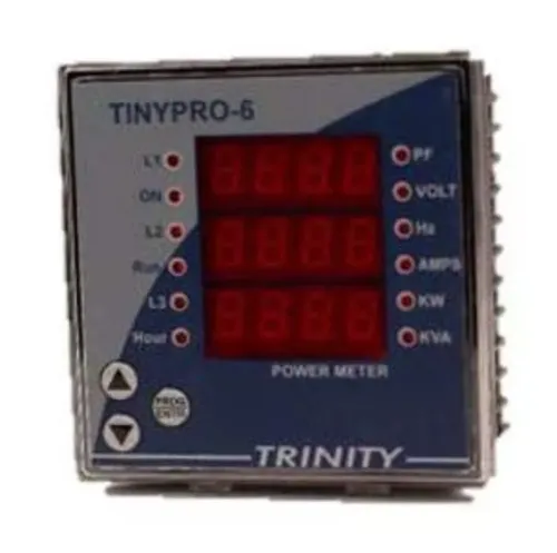
 | MULTIFUCTION METER MODEL: TINY PRO 6 MULTIFUCTION METER MODEL: TINY PRO 6 Features 1. Multiparameter monitoring. 2. All parameters with default accuracy class 1.0 3. Measures V, I, KW and Hz 4. View product → |
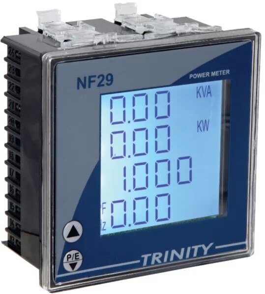 | MULTIFUCTION PANEL METER MODEL: NF29 MULTIFUCTION PANEL METER MODEL: NF29 MFM With Customized LCD, With THD View product → |
 | LOW VOLTAGE POWER DISTRIBUTION PRODUCTS Siemens make ACB 3WJ 630 AMP TO 4000 AMP View product → |