A digital voltmeter is suitable only when its input range, wiring configuration, accuracy specification and physical dimensions match the installation. By the end, you will have a practical way to define the measurement, check safety and panel fit, compare quotations and identify whether a supplier can configure the instrument correctly.
Key takeaways
- Specify maximum normal voltage, wiring configuration and line-to-line or line-to-neutral measurement.
- Use a PT or VT connection when system voltage exceeds the meter’s direct-input rating.
- Compare accuracy class, resolution and installation-related errors—not display digits alone.
- Give suppliers panel cutout dimensions, depth, display conditions and operating environment.
Define the Voltage and Wiring the Meter Must Measure
Specify the digital voltmeter voltage range from the highest normal reading, not the nominal system label. State whether you need line-to-neutral voltage, line-to-line voltage, or both, then give the number of voltage inputs, neutral connection, wiring configuration, and required three-phase voltage measurement.
| Configuration | Specify to the supplier | Typical application |
|---|---|---|
| Single-phase L-N | One phase input, neutral reference, L-N range | Control or distribution circuit monitoring |
| Single-phase L-L | Two phase conductors, L-L range, no neutral reference | Phase-to-phase supply monitoring |
| Three-phase, three-wire | Three voltage inputs, phase sequence, L-L measurement, no neutral | Motors and delta systems |
| Three-phase, four-wire | Three voltage inputs plus neutral, L-N and L-L accuracy | Star-connected distribution and generator panels |
A 25–500 V AC range does not suit every installation. For measured voltage below 25 V AC, request low-voltage input accuracy and confirm that the meter’s input impedance will not load a PLC, sensor, or relay circuit.
Above 500 V AC, specify the PT or VT ratio, secondary voltage, burden, insulation level, fuse protection, and internal scaling; a 100:1 transformer converts 6.6 kV to 66 V. Confirm the continuous input limit, IEC 61010 CAT III or CAT IV rating, working voltage, and input-to-supply isolation.
Decide Between Direct Measurement and a PT or VT Connection
Connect the meter directly only when the circuit voltage, including expected transients, remains within its direct measurement range and safety rating.
A label such as 25–500 V AC does not make a meter suitable for every 500 V panel: check its IEC 61010 measurement category, such as CAT III or CAT IV, and its working-voltage rating.
Below 25 V AC, verify the meter’s low-end accuracy, resolution and input impedance. A conventional 10 MΩ input suits many control-circuit measurements; a LoZ mode can suppress ghost voltage but load a PLC, sensor or relay circuit and collapse its reading.
Use a potential transformer when the primary voltage exceeds the meter’s direct-input range. Give the supplier these details:
- Primary voltage and whether the measurement is line-to-neutral or line-to-line
- PT ratio, such as 100:1, which converts 6.6 kV to a 66 V secondary
- Secondary voltage and frequency
- Meter input burden, in VA or impedance
- PT and meter insulation level, including the required working-voltage rating
- Fuse protection on the PT secondary and the meter’s input protection
- Whether the displayed value is scaled internally, or requires a programmed multiplier
The meter still connects to the PT secondary, so specify its permitted overvoltage and insulation for that circuit. For three-phase measurement, state the number of PT inputs, neutral requirement and supported wiring configuration; a single-phase L-N input cannot automatically measure a three-phase system.
Compare Accuracy, Resolution and Real-World Measurement Error
Request a voltage-specific accuracy of ±0.5% of reading for utility monitoring and motor panels, ±0.25% for generator and capacitor-bank diagnostics, and ±0.1% to ±0.25% for protection-circuit checks or process instrumentation. Treat these as purchasing targets, then confirm the supplier’s test conditions.
| Application | Starting accuracy target | Why it matters |
|---|---|---|
| Utility monitoring | ±0.5% of reading | Suitable for tracking supply variation and operating trends |
| Motor panels | ±0.5% of reading | Identifies phase imbalance without paying for laboratory precision |
| Generator panels | ±0.25% of reading | Improves comparison between phases and operating states |
| Capacitor banks | ±0.25% of reading | Helps detect abnormal voltage during switching |
| Protection circuits | ±0.1% to ±0.25% | Limits error during trip-circuit and reference-voltage checks |
| Process instrumentation | ±0.1% to ±0.25% | Supports tighter control-loop verification |
Do not accept “accuracy class 1.0” as the complete answer on a multifunction meter. Ask for the voltage-channel specification in the form ±(% of reading + digits), covering the selected measurement range, display resolution, test frequency and reference temperature.
A 600 V meter showing 0.1 V has impressive display resolution, but its guaranteed error could still be several volts near the bottom of that range.
Check repeatability separately: stable repeated readings do not prove that the value is correct. For inverter, PWM or rectifier-fed circuits, require True-RMS voltage measurement, stated bandwidth and crest-factor limits. Also request IEC 61326-1 EMC evidence; contactors and drives can add installed-panel error that a laboratory accuracy figure does not reveal.
Check Panel Fit, Viewing Conditions and Operating Environment
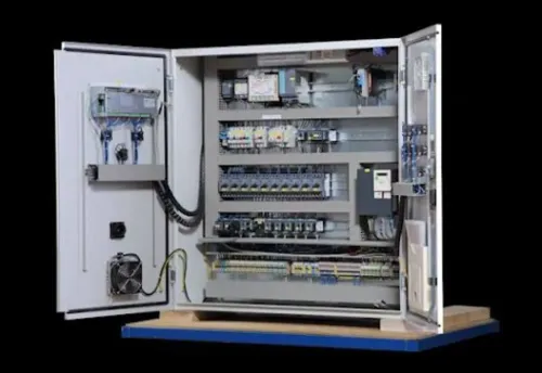
Measure the existing opening before choosing a replacement. Confirm the panel cutout, bezel size, maximum rear clearance, mounting method, terminal locations, wiring-duct space and the direction needed to remove terminals or reach retaining clips. A nominal “96 mm” case or “DIN rail” label does not guarantee interchangeability.
Ask the supplier to confirm these installation dimensions and conditions:
- Panel cutout dimensions and tolerance, bezel size, gasket requirement and front IP or NEMA rating.
- Maximum rear depth, terminal projection, terminal orientation and clearance for bend radius, ferrules and fuses.
- Seven-segment LED display versus LCD, including digit height, viewing angle, backlight, contrast and visibility in sunlight or a dark control room.
- Operating temperature, humidity range, condensation limit and whether the rear terminals require a protected enclosure.
- IEC 61010 measurement category and working-voltage rating, such as CAT III or CAT IV at the intended voltage.
- IEC 61326-1 EMC classification or equivalent test evidence for panels containing contactors, variable-frequency drives or switching power supplies.
Treat front and rear protection as separate specifications. An IP-rated bezel does not protect rear terminals from washdown, conductive dust or condensation. A gasket helps only when the cutout, door thickness and mounting pressure match the manufacturer’s limits.
Check the installed viewing position with the door closed and equipment energised. If the display is unreadable from the operator’s normal position, a correctly accurate meter still fails its job. Confirm service access before ordering; a meter that fits but forces removal of ducting or adjacent devices increases maintenance time.
Turn the Requirements into a Comparable Supplier Quotation
Before placing an order, require every digital voltmeter supplier to complete the same technical schedule and attach evidence, not just a catalogue accuracy figure.
1. State the measurement circuit: line-to-neutral or line-to-line, single- or three-phase, number of inputs, neutral requirement, supported wiring, and phase-to-phase accuracy. Identify whether 25–500 V AC is a direct-input range. If the system is below 25 V AC or above 500 V AC, specify the required input range or transformer connection.
2. Give the measurement error specification as ±(% of reading + digits), with resolution, measurement range, test frequency, and reference temperature. Ask for voltage accuracy separately from a multifunction meter’s overall class 1.0 rating. Include repeatability if readings will support protection or process decisions.
3. For a PT connection, state the primary-to-secondary ratio, secondary voltage, burden in VA, insulation level, accuracy class, fuse rating, and wiring diagram. The quotation must show the scaled display value and the meter’s continuous input limit.
4. Require IEC 61010 measurement category and working-voltage ratings, such as CAT III or CAT IV at the stated voltage. The quotation must also identify altitude limits, environmental restrictions, required fuses, and any external protection; a CAT rating does not permit exceeding the continuous input limit.
5. For panels containing contactors, drives, or switching supplies, request IEC 61326-1 classification or equivalent EMC test evidence, including conducted and radiated immunity results. Also record enclosure cut-out, terminal layout, input impedance, and whether LoZ mode could load a PLC or sensor circuit.
Contact Electrical & Automation Pvt Ltd can use this same schedule when comparing a single-phase, three-phase, or custom panel quotation.
Related products
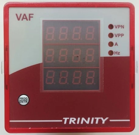 | DIGITAL PANEL METER, MODEL:VAF DIGITAL PANEL METER, MODEL:VAF A VAF meter (Voltage, Amperage, Frequency) is a digital panel-mounted instrument used to measure, monitor, and display key electrical parameters in... View product → |
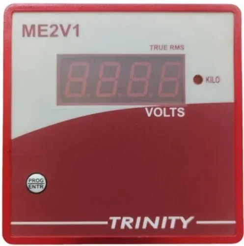
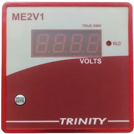 | SINGLE PHASE VOLTMETER (ME2V1) SINGLE PHASE VOLTMETER (ME2V1) Volts (25-500V AC) of one phase on 0.56" seven segment LED View product → |
Frequently asked questions
How do you define the voltage range for a digital voltmeter?
Base the range on the highest normal reading, then state whether the meter measures line-to-neutral voltage, line-to-line voltage, or both. Include the number of voltage inputs, neutral connection and three-phase wiring configuration.
When should a digital voltmeter use a PT or VT connection?
Use a potential transformer or voltage transformer when the system voltage exceeds the meter’s direct-measurement input rating. Provide the transformer primary and secondary voltages so the supplier can configure the scale correctly.
What is the difference between accuracy and resolution in a digital voltmeter?
Resolution is the smallest displayed increment; accuracy is the permitted measurement error. Compare the accuracy specification across the expected voltage range and account for transformer ratio error, wiring drops and installation conditions.
What panel requirements should you give a digital voltmeter supplier?
Provide the panel cutout width and height, instrument depth, mounting method, terminal access, display size, viewing distance, lighting conditions, ambient temperature, humidity and enclosure requirements.
Related products
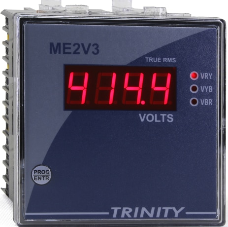 | THREE PHASE VOLTMETER (ME2V3) Volts (25-500V AC) of three phase on 0.56" seven segments LED. View product → |
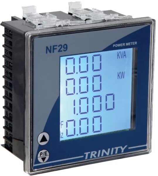 | MULTIFUCTION PANEL METER MODEL: NF29 MULTIFUCTION PANEL METER MODEL: NF29 MFM With Customized LCD, With THD View product → |
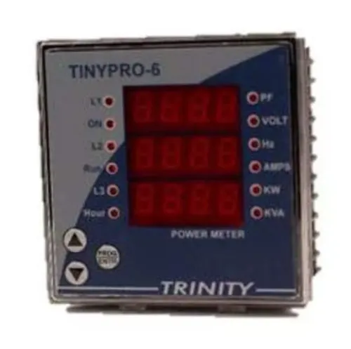
 | MULTIFUCTION METER MODEL: TINY PRO 6 MULTIFUCTION METER MODEL: TINY PRO 6 Features 1. Multiparameter monitoring. 2. All parameters with default accuracy class 1.0 3. Measures V, I, KW and Hz 4. View product → |