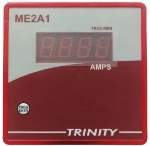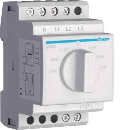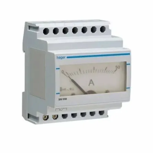
A panel voltmeter can fit the cutout and still be wrong for the circuit, unsafe for the fault level, or too inaccurate for the reading you need. Before ordering, you will be able to give the supplier a defined electrical input, protection method, accuracy requirement, installation environment, and documentation checklist.
Key takeaways
- Confirm whether the meter measures line-to-neutral, line-to-line, or both.
- Specify accuracy, resolution, burden, and display requirements—not only digit count.
- Check CAT rating, isolation, fuse protection, and the panel’s fault level.
- Get written wiring, mounting, and abnormal-condition instructions before commissioning.
Confirm exactly what voltage the meter will measure
Confirm that the meter’s input matches the voltage present in your panel, the connection available, and the installation limits. Ask the single phase voltmeter supplier whether it accepts line-to-neutral voltage, line-to-line voltage measurement, or either connection.
Check the panel schematic before ordering and identify:
- Phase terminal, neutral terminal, protective earth, and any voltage-transformer secondary.
- Whether a neutral conductor is actually available.
- Whether the circuit is floating two-wire, split-phase, or connected through a potential transformer.
Do not assume a single-phase meter suits each arrangement. Give the supplier the nominal voltage, allowable sustained overvoltage, and frequency, such as 230 V AC, 50 Hz, line-to-neutral.
| Specification | Ask for this exact information | Why it matters |
|---|---|---|
| Continuous input range | Permitted voltage during normal operation | Prevents damage from sustained overvoltage |
| Short-duration overload | Voltage and duration the input withstands | Covers switching events without confusing them with normal operation |
| Accuracy range | Voltage range over which accuracy is guaranteed | A 25–500 V AC panel voltmeter input range does not ensure equal accuracy at every point |
If a potential transformer is installed, provide its secondary voltage and ratio. Confirm the required burden, transformer accuracy class, phase-angle error, grounding arrangement, and whether the meter can be scaled for that ratio. Also ask whether the voltage input needs separate fusing and whether it is isolated from auxiliary power and communications terminals.
Define the accuracy you need, not just the number of digits
A panel meter accuracy claim is incomplete without its test conditions. Ask the supplier to prove the displayed value using a calibration report or test record for your input voltage, rather than quoting only the number of display digits.
Request the exact accuracy statement:
- Percentage of reading, percentage of full scale, or a combined form such as ±(0.5% of reading + 2 digits).
- Reference temperature, frequency range, input voltage, warm-up time, and calibration conditions.
- Measurement resolution at your actual system voltage and the minimum input voltage that remains meaningful.
- Zero-display threshold, undervoltage indication, and behaviour after loss of one conductor.
| Measurement method | What it means | When it applies |
|---|---|---|
| Average-responding measurement | Measures an averaged waveform and calibrates it for a sine wave | Clean 50 or 60 Hz supply |
| True-RMS voltmeter | Calculates heating-equivalent RMS voltage across waveform shapes | Variable-frequency drives, switched-mode supplies, or phase-angle controllers |
For distorted loads, obtain the true-RMS voltmeter’s frequency bandwidth and crest-factor limit. Also request response time, update interval, damping, and peak-capture behaviour. A damped display can hide a short undervoltage event, while a fast display can turn normal waveform variation into distracting movement.
Verify protection, isolation, and the meter’s safety category
A 500 V measuring range does not make a panel meter safe on a 500 V distribution circuit. A CAT III panel meter must state the maximum voltage permitted in its CAT III rating, not just its display or measurement range.
1. Ask for the measurement category and maximum rated voltage: CAT II, CAT III, or CAT IV. Confirm the permitted continuous input, short-duration overload, surge withstand, short-circuit withstand, input impedance, and input burden separately.
Obtain the supplier’s stated result when the input exceeds the continuous rating: fault indication, zero, retained reading, permanent damage, or a defined safe failure.
2. Obtain the exact voltmeter input protection requirement. Record the fuse or circuit-breaker type, recommended ampere rating, fuse class, maximum upstream interrupting rating, and whether every voltage input needs separate short-circuit protection. Confirm whether the meter accepts a separately fused signal or direct bus connection; terminal insulation does not prove fault-current withstand.
3. Confirm galvanic isolation between the voltage input and auxiliary power, communications terminals, relay outputs, and chassis. If isolation is absent, obtain the allowable common-mode voltage and exact wiring restrictions; a low-voltage control wire can otherwise carry hazardous potential.
4. During installation, isolate the panel, apply site lockout/tagout, prove dead with an approved test instrument, and use required arc-flash controls. A display is indication, not proof that a circuit is dead.
5. Check the installation against the applicable edition and site scope of IS 732 and Central Electricity Authority safety regulations before recording compliance. Ask what happens after overrange, auxiliary-power loss, loss of neutral, or an open voltage-transformer secondary.
Match the physical installation and wiring details to the panel
A meter fits only when its body, terminals, and wiring space match the panel. Request the panel meter cutout size, bezel dimensions, mounting depth, mounting-clip dimensions, terminal arrangement, and minimum rear clearance before ordering.
| Check | Request from supplier | Resolve before installation |
|---|---|---|
| Voltmeter terminal capacity | Solid and stranded conductor range, ferrule type, insulation strip length, and tightening torque | Wire or ferrule outside the stated range |
| Safety spacing | Creepage and clearance, pollution degree, and insulation category | Crowded terminals or contaminated environments |
| Environment | Panel meter operating temperature, storage temperature, humidity, altitude, vibration limit, and IP rating | Enclosure conditions beyond the meter’s limits |
| Compliance | IEC 61010-1 safety, IEC 61326-1 EMC, IEC 60529 ingress, and assembly compatibility such as IEC 61439 | Generic “industrial use” wording without jurisdictional approval |
Compare the panel meter operating temperature with the temperature measured inside the enclosure, not the room temperature. Contactors and drives heat a crowded panel, and accuracy, display operation, and auxiliary-power limits can derate outside the reference temperature.
Before wiring, obtain the complete diagram and terminal schedule, then:
- Identify every voltage-input, auxiliary-power, output, communication, and earth terminal.
- Confirm the specified fuse or circuit-breaker and whether each voltage input needs separate short-circuit protection.
- Isolate and prove the supply dead, fit the required ferrules, and tighten terminals to the stated torque.
- Route voltage conductors separately from control and communication wiring.
Require written answers for abnormal conditions and commissioning
Do not commission the meter on a verbal promise that it will “handle” an abnormal condition. Require single phase voltmeter documentation that states what the display shows and what the input circuit can survive.
1. Ask for written behavior after auxiliary-power interruption, input overrange, loss of neutral, undervoltage, and communication failure. The specification must identify whether the meter fault indication appears, the last value remains, the display reads zero, or the condition can damage the meter.
2. Treat a voltage transformer open secondary as a safety condition: it can generate hazardous voltage. Confirm the required secondary fuse, burden, grounding method, and short-circuit protection. Ask whether the voltage input is designed for a separately fused signal or direct connection to a bus.
3. Obtain the installation drawing, terminal schedule, protective-device specification, accuracy statement, calibration method, category rating, environmental limits, and panel voltmeter commissioning checklist. Record the measured line-to-neutral or line-to-line connection, fuse rating, conductor size, terminal torque, and post-installation voltage check.
4. During commissioning, verify the supplier’s stated minimum input voltage, loss-of-conductor behavior, and display threshold against the installed circuit. Do not infer fault-current withstand from the terminal voltage rating.
A business-to-business supplier such as Contact Electrical & Automation Pvt Ltd is useful when it defines the meter, protection, wiring arrangement, and records as one package. Require every answer in writing; supplier experience does not replace a matching data sheet or site safety review.
Related product
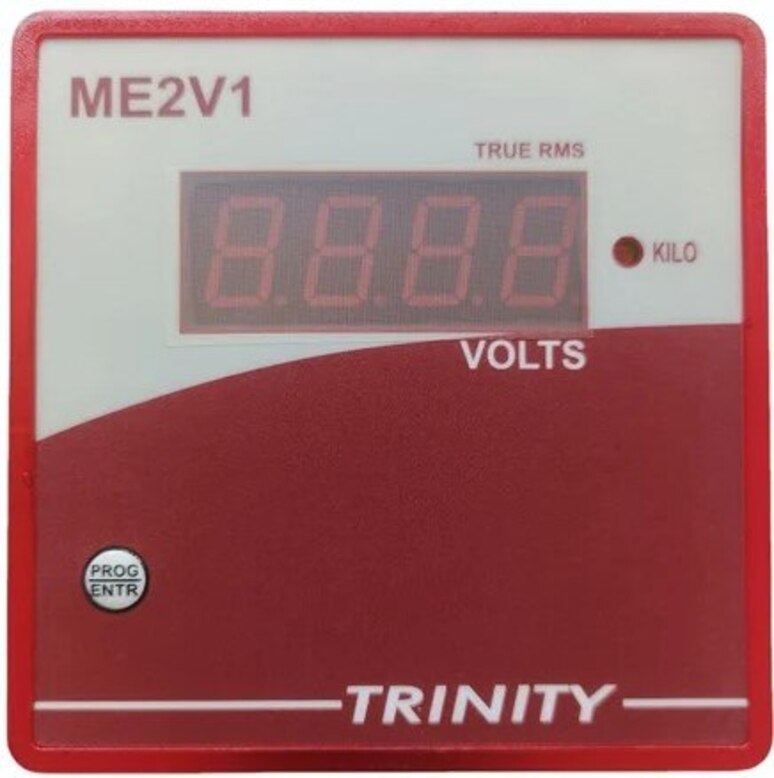
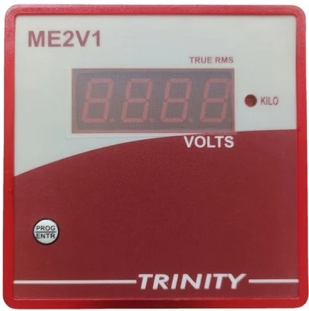 | SINGLE PHASE VOLTMETER (ME2V1) SINGLE PHASE VOLTMETER (ME2V1) Volts (25-500V AC) of one phase on 0.56" seven segment LED View product → |
Frequently asked questions
What voltage connection should you confirm with a single-phase voltmeter supplier?
Confirm whether the meter accepts line-to-neutral voltage, line-to-line voltage, or either connection, then match its input range to the panel voltage.
How do you define the accuracy needed for a panel voltmeter?
Specify measurement accuracy across the operating voltage range, display resolution, frequency range, and any tolerance required for alarms or operational decisions.
What safety details must you verify before installing a panel voltmeter?
Check the meter’s CAT rating, insulation and isolation details, fuse or circuit-breaker protection, terminal ratings, and suitability for the panel’s prospective fault current.
Which physical and wiring details should you confirm before ordering?
Match the cutout dimensions, mounting depth, terminal arrangement, wire size, polarity, connection diagram, auxiliary supply, and clearance to the panel layout.
What should the supplier document for commissioning and abnormal conditions?
Require written instructions for overvoltage, loss of neutral, reversed polarity, frequency outside range, blown fuses, startup checks, and acceptable commissioning readings.