A single-phase ammeter’s headline display range does not tell you which current transformer will produce an accurate reading. By matching the CT ratio, secondary current, burden, accuracy class, wiring and operating conditions, you can ask suppliers for a complete measurement set rather than a meter with an unexplained number on its display.
Key takeaways
- Choose the CT primary for maximum operating, starting, and planned future current.
- Match the CT secondary rating to the ammeter input, commonly 1 A or 5 A.
- Check burden, accuracy class, and secondary protection before accepting a quotation.
- Test accuracy at low load and with distorted waveforms before finalising the supplier.
Calculate the CT ratio from the current your feeder will actually carry
A 0–5,000 A display does not mean the ammeter measures 5,000 A directly. Choose the CT primary from the feeder’s actual operating range: maximum load current, expected starting current, and planned future capacity.
For a feeder expected to reach 320 A, a 400/5 A CT gives headroom without sacrificing as much low-current resolution as a 1,000/5 A CT. Do not size the CT from the meter’s headline display range.
| CT option | Suitable feeder range | Main trade-off |
|---|---|---|
| 200/5 A | Loads near 200 A | Better resolution, but inadequate above 200 A |
| 400/5 A | Loads reaching 320 A | Headroom for the stated maximum load |
| 1,000/5 A | Loads approaching 1,000 A | Poorer resolution at 80–150 A |
Use this CT ratio calculation: select a primary rating above the maximum load current, then check whether starting current will saturate the core or exceed the meter’s intended range.
If a motor draws 600 A for several seconds while its running current is 250 A, tell the supplier whether you need an accurate starting-current reading or only stable running-current measurement.
Request accuracy data across your real operating range, not only at rated current. A 1,000/5 A CT can show an acceptable full-load result while giving an unreliable reading at 80 A. Include future capacity before ordering; replacing a CT inside a live panel is not a simple display upgrade.
Match the CT secondary to the ammeter input and verify the scaling
Confirm the ammeter input before approving the CT.
A meter designed for a 1 A CT secondary is not interchangeable with one designed for a 5 A CT secondary; connecting a 5 A CT to a 1 A input can overload the input, while connecting a 1 A CT to a 5 A input can distort the reading.
Ask the supplier to state these details in writing:
- The ammeter input range, including whether it accepts 1 A, 5 A, or both.
- The selected CT secondary rating and the exact primary-to-secondary ratio, such as 200/5 A or 200/1 A.
- Whether the ME2A1 external CT configuration accepts the chosen secondary and permits the required primary scaling.
Check the calculation yourself: displayed primary current equals measured secondary current multiplied by the CT ratio.
A 200/5 A CT producing 3.5 A at its secondary must display 140 A. A 0–5,000 A display does not prove that the meter accepts a 5,000 A direct input; the supplier must configure that display from the CT signal.
Request accuracy data at your normal low and high operating currents, not only at rated current. Also confirm the CT burden includes the meter, terminals, test switch and complete cable loop, and preserve the CT’s polarity markings when wiring it.
Specify CT burden, accuracy class and safe secondary-circuit protection
Specify a CT burden VA that exceeds the complete connected load, not just the meter burden. Add the ammeter input, terminal blocks, test switch, and both conductors in the secondary loop; long or small conductors increase the burden and can cause ratio error or saturation.
Ask the supplier to state rated burden in VA at the selected 1 A or 5 A secondary current.
| Specification | What it controls | What to request |
|---|---|---|
| CT burden VA | Accuracy under connected load | Rated VA, calculated loop burden, and conductor length |
| Metering CT class | Ratio and phase accuracy | 0.2, 0.2S, 0.5, or 0.5S at the required current range |
| Protection CT 5P 10P PX | Fault-current performance | Use only for protection; do not substitute it for a metering CT |
A metering CT class describes measurement performance; 5P, 10P, and PX describe protection behaviour during faults. A protection CT with the correct ratio can still give an unsuitable process or revenue reading, especially at low load. Request accuracy data at the operating current that matters, not only at rated current and nominal burden.
Protect the secondary circuit with a dedicated CT shorting terminal block or test switch. Never disconnect an energized CT secondary: dangerous voltage can damage insulation and injure someone. Earth the CT secondary at one designated point, identify the S1 and S2 terminals, and specify frequency, insulation level, and the applicable standard in the quotation.
A quote stating only “400/5 A CT” is incomplete.
Test the supplier’s recommendation against low current, distorted waveforms and future loads
At the same 5 A secondary rating, a 100/5 CT provides four times the low-current signal of a 400/5 CT. Compare each proposal against your minimum, normal and maximum current, not against the ammeter’s 0–5 A input alone.
- 100/5 A: 20 A primary produces 1 A secondary; 100 A produces 5 A.
- 200/5 A: 20 A primary produces 0.5 A secondary; 200 A produces 5 A.
- 400/5 A: 20 A primary produces 0.25 A secondary; 400 A produces 5 A.
Ask the supplier for accuracy data at your actual low-current point, such as 20, 50 and 100 A, rather than a single result at rated current. This exposes poor low-current resolution and ratio error that a 400/5 CT can hide.
Request the CT’s excitation or saturation data at the specified burden, because CT saturation can distort the displayed current during overloads or starting.
For a variable-frequency drive current, rectifier load or switch-mode supply, require a true-RMS ammeter with a stated frequency range and crest-factor rating. A CT ratio alone does not prove accurate measurement of a distorted waveform. Ask for a test reading at the expected waveform and load.
State present minimum and maximum current, overload duration and future capacity separately. Oversizing for an uncertain future load can make today’s normal current unreadable; select a ratio that preserves resolution, then plan a revised CT if expansion exceeds it.
Send a complete specification and compare matched supplier quotations
Give every supplier the same installation brief: feeder maximum and expected future current, single-phase wiring, system frequency, selected 1 A or 5 A secondary, CT ratio, measurement purpose, accuracy class, rated burden in VA, insulation level, applicable standard, and whether the CT is solid-core or split-core.
Include the panel cut-out dimensions, meter supply voltage, terminal arrangement, cable length, and a CT wiring diagram showing P1/P2, S1/S2, polarity, and the complete secondary loop.
Ask each supplier to include these items:
- Ammeter, CT, mounting hardware, terminal blocks, labels, and commissioning details
- A shorting terminal block or test switch that prevents an energized CT secondary from opening
- Selector-switch wiring if one ammeter reads several CTs
- Split-core installation limits, including conductor centering, orientation, and closed-core condition
Contact Electrical & Automation Pvt Ltd can be asked to confirm whether its proposed single-phase ammeter is being quoted with the matching CT, terminals, and scaling rather than as a display unit alone.
| Item | Complete quotation | Warning omission |
|---|---|---|
| CT data | Ratio, 1 A or 5 A, burden, class, frequency, insulation level, standard | “400/5 A CT” only |
| Meter interface | Input current, scaling, supply, cut-out | Display range only |
| Safety | Shorting device and wiring diagram | No secondary protection |
| Installation | Polarity and selector arrangement | No connection details |
Related product
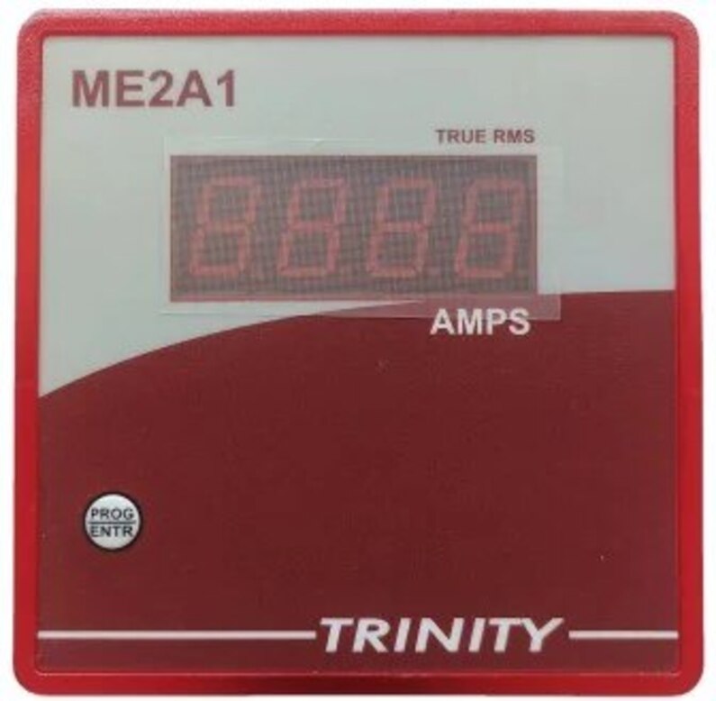
 | SINGLE PHASE AMMETER (ME2A1) AMPS (0-5000A AC) Of One phase on 0.56" seven segment LED View product → |
Frequently asked questions
How do you calculate the CT ratio for a single-phase ammeter?
Base the CT primary on the feeder’s maximum operating current, expected starting current, and planned future capacity. Select a ratio that covers those conditions without making normal load too small to read accurately.
How do you match a CT secondary to an ammeter?
Confirm whether the ammeter accepts a 1 A or 5 A CT secondary, then verify its programmed or printed scaling against the CT ratio. A 100/5 CT requires an ammeter configured to display the corresponding primary current.
What CT specifications should a supplier quotation include?
Request the CT burden in VA, accuracy class, rated primary and secondary current, insulation rating, frequency, and a safe method for protecting the secondary circuit.
How should you test a supplier’s ammeter recommendation?
Check the reading at low current, during starting or high-load conditions, with distorted waveforms, and against planned future loads. Confirm that the CT and ammeter remain within their specified limits.