A distribution board cannot be sized safely by adding every nameplate current. You need a design current based on operating duty, a fault level based on the supply system, and protection that works with the cables, motors and upstream devices. By the end, you will know which calculations, data and verification documents to demand from a supplier before approving the board.
Key takeaways
- Calculate design current from demand load, then check motor starting current separately.
- Separate lighting, socket, motor and sensitive electronic loads before sizing circuits.
- Check breaker ratings against cable capacity, prospective fault current and assembly withstand ratings.
- Ask the supplier to review schedules, protection coordination and terminal capacity before manufacture.
Turn connected loads into a defensible design current
Rate the feeder and incomer from design current, not from the arithmetic total of nameplate ratings. Connected load is the maximum installed load; demand load is the portion expected to operate together under the actual process schedule. Use demand load to establish normal running current, then check motor starting current separately.
| Quantity | Use in the design | Common mistake |
|---|---|---|
| Connected load | Establishes installed capacity and future loading | Adding every nameplate current as if all loads run together |
| Demand load | Establishes expected steady feeder and incomer current | Applying an arbitrary diversity factor |
| Starting current | Tests voltage drop and protective-device operation | Treating it as continuous running current |
For a three-phase load, the current formula is I = kW × 1,000 ÷ (√3 × voltage × power factor × efficiency). Use efficiency for a motor or other conversion equipment.
For a kVA load, use I = kVA × 1,000 ÷ (√3 × voltage); power factor and efficiency are already represented in the kVA figure. Calculate each load at its actual operating voltage and power factor before summing demand currents.
- Request operating schedules, interlocks and simultaneous-start conditions.
- Check the highest motor starting current against feeder length, conductor impedance and starting voltage at the motor terminals.
- Select the next suitable feeder and incomer rating above the calculated design current, then confirm cable ampacity, voltage drop and breaker settings.
- Record the prospective fault current separately; connected load does not determine the board’s short-circuit withstand.
Separate load types before choosing circuits and board capacity
A continuous load needs its own design current, while an intermittent load can use its actual duty cycle and operating schedule. Separate lighting load, motor load, capacitor bank and nonlinear load into distinct outgoing ways; combining unlike duties hides inrush, heat and harmonic effects.
| Load type | Board and circuit consequence | Design check |
|---|---|---|
| Continuous load | Reserve conductor, breaker and busbar capacity for sustained heating | Apply the specified continuous-duty rule |
| Intermittent load | Base diversity on interlocks and operating schedules, not an arbitrary factor | Confirm which loads run together |
| Lighting load | Provide grouped ways and account for LED-driver inrush | Check starting current and voltage drop |
| Motor load | Allow for starting current and use the motor load classification factor | Check starting voltage and overload protection |
| Capacitor bank | Use dedicated switching and protection; switching creates inrush | Check resonance and harmonic interaction |
| Nonlinear load | Expect triplen harmonics from drives, LED drivers and power supplies | Include harmonics in neutral sizing and temperature-rise calculations |
Do not reduce a neutral from phase current alone. Triplen harmonics add in the neutral, so obtain the harmonic spectrum before selecting a four-pole device or smaller neutral.
Specify spare ways, termination space and documented busbar capacity for expansion. A larger incomer is not enough: added devices can exceed heat limits, cable space or the board’s fault rating. Reserve enclosure volume and thermal allowance, then confirm the completed assembly remains suitable when those spare ways are populated.
Match the breaker and assembly to current, fault level and cable limits
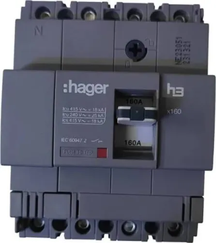
Select an MCCB or ACB whose voltage rating suits the system, continuous current rating covers the design current, and breaking capacity exceeds the prospective short-circuit current at its installation point. A larger ampere frame alone does not solve a fault-rating problem.
- Check Ib ≤ In ≤ Iz: Ib is the design current, In is the breaker’s rated current or setting, and Iz is the cable ampacity after grouping, ambient-temperature, installation-method and enclosure derating. If In exceeds Iz, the cable can overheat before the breaker operates.
- Calculate prospective short-circuit current at the board, using the transformer rating, source impedance, conductor length and conductor impedance. Compare it with the breaker’s ultimate breaking capacity and service breaking capacity; do not assume the latter equals the former.
- Confirm the complete assembly’s SCCR or declared short-circuit withstand rating, including busbars, supports, enclosure and connections. An MCCB or ACB with adequate interrupting capacity does not automatically give the distribution board the same rating.
- Require IEC 61439 design verification and routine verification. The evidence must cover temperature rise, clearances, creepage, dielectric strength, protective-circuit continuity and short-circuit performance.
Choose the ACB or MCCB after checking enclosure heat dissipation, device spacing, ventilation and simultaneous loading. For expansion, specify spare ways, busbar and termination capacity, heat allowance, and a documented fault-rating basis; an empty way is unusable if it breaches temperature, cable-space, SCCR or selectivity limits.
Make protection perform the right function in the right order
A breaker that trips for every fault is not a coordinated protection scheme. Separate overload protection, short-circuit protection, earth-fault protection, motor overload, and isolation so each device acts on the fault it is designed to clear.
| Function | Device or setting | What it does |
|---|---|---|
| Overload | Thermal or electronic long-time trip | Protects conductors from sustained excess current |
| Short-circuit | Magnetic or short-time and instantaneous trip | Clears high fault current before severe damage |
| Earth-fault | Earth-fault release or RCD | Detects current leaving the intended circuit path |
| Motor overload | Overload relay | Protects the motor from prolonged overcurrent and phase loss |
| Isolation | Switch-disconnector or breaker with isolation rating | Provides a safe, visible means to de-energise equipment |
An RCD is not interchangeable by sensitivity alone. Type AC detects sinusoidal alternating residual current; Type A also detects pulsating DC. Drives and rectifiers can require Type F or Type B, based on the equipment manufacturer’s instructions.
Use this coordination procedure:
1. Calculate prospective short-circuit current at the board, then check the assembly withstand rating and each breaker’s interrupting rating. A breaker’s rating does not automatically establish the distribution board’s SCCR.
2. Plot upstream and downstream time-current curves. Confirm selectivity across the actual current range; different ampere ratings do not guarantee it. Check the instantaneous setting because high fault current can defeat time discrimination.
3. For each motor, match starting current, overload-relay range, contactor utilization category, and short-circuit coordination. Specify Type 1 coordination when repair is acceptable; specify Type 2 coordination when the starter must remain suitable for further service after the test.
4. Coordinate the incomer, bus coupler, and outgoing breakers so the nearest device trips first, including each bus-coupler operating state. Confirm the result from manufacturer tables or tested combinations, not from assumptions.
Use the supplier’s design review to close the gaps before manufacture
A board can carry every connected load on paper and still fail at site: a motor start can depress voltage, a hot enclosure can force derating, or an open CT secondary can create a dangerous high voltage. Require a supplier design review before fabrication, supported by calculations and test records.
1. Give the supplier feeder lengths, conductor sizes and impedance, motor starting current and duration, power factor, ambient temperature, installation altitude, and simultaneous-load assumptions. Require the voltage drop and motor starting calculations, including the effect on contactor holding, lighting and remote equipment.
2. Require the motor schedule to show overload-relay range, contactor utilization category, short-circuit coordination, and whether IEC Type 1 or Type 2 coordination is specified. Obtain the IEC 61439 design verification evidence for temperature rise, dielectric properties, clearances, creepage, short-circuit withstand and protective-circuit continuity, plus routine verification records for the completed board.
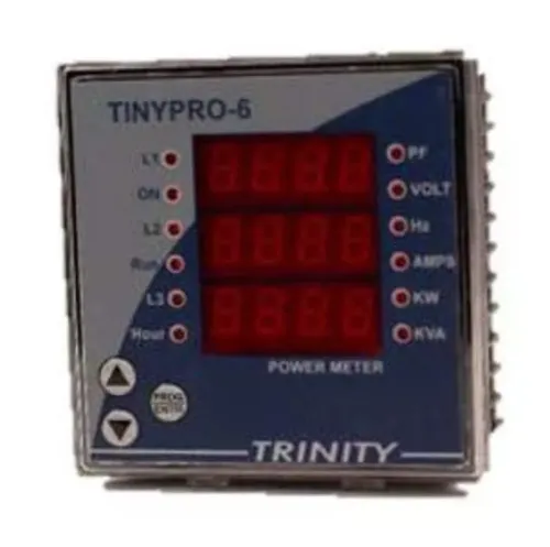
3. For metering, confirm each CT ratio, accuracy class, burden, polarity, frequency and protection requirement. Check that test links or shorting terminals protect every CT secondary; energising a transformer with its secondary open can produce hazardous voltage.
4. State the enclosure material, ambient conditions, condensation, chemicals, sunlight and corrosion exposure alongside the enclosure IP code. IP protection does not prove chemical or UV resistance. Mark spare ways, spare busbar capacity, cable-entry space and physical room for future devices.
Contact Electrical & Automation Pvt Ltd can use this review to resolve whether a proposed MCCB, ACB or switch-disconnector arrangement fits the calculated duty before manufacture.
Related products
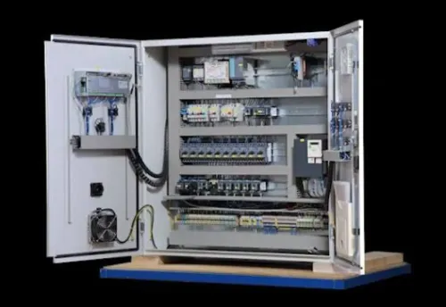
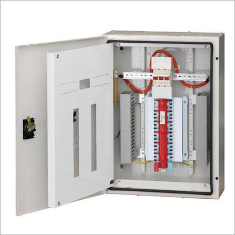
 | DISTRIBUTION BOARD & CONTROL PANEL DISTRIBUTION BOARD & CONTROL PANEL We Design and Market: Low Voltage: custom-built switchboards for industrial & other application. View product → |
 | LOW VOLTAGE POWER DISTRIBUTION PRODUCTS Moulded Case Circuit Breakers (MCCB) Moulded Case Circuit Breakers (MCCB) 3VA/3VM/3VJ - 16 AMP To 1600 AMP View product → |
Frequently asked questions
How do you calculate the current for a distribution board?
Use the expected demand load to establish normal running current rather than adding every nameplate rating. Check motor starting current separately before selecting the feeder and incomer.
Why should load types be separated before choosing circuits?
Lighting, socket outlets, motors, heating and sensitive electronic equipment have different demand, starting, harmonic and protection requirements. Separating them produces more suitable circuit ratings and improves fault isolation.
What must be checked when matching breakers and a distribution board?
Check the breaker rating against design current and cable capacity, then verify the board and breaker interrupting ratings against prospective fault current. Confirm the assembly can withstand the expected short-circuit stress.
What should a distribution board supplier review before manufacture?
Ask for a review of the load schedule, circuit grouping, incomer and feeder ratings, cable sizes, fault level, protection coordination, spare capacity, enclosure requirements and terminal arrangements.
Related products
 | LOW VOLTAGE POWER DISTRIBUTION PRODUCTS Switch Disconnector Fuse Unit (SDF) Switch Disconnector Fuse Unit (SDF) 32 amp to 800 amp View product → |
 | LOW VOLTAGE POWER DISTRIBUTION PRODUCTS Siemens make ACB 3WJ 630 AMP TO 4000 AMP View product → |
 | LOW VOLTAGE POWER DISTRIBUTION PRODUCTS On load Changeover Switches View product → |
 | MOTORS CONTROL PRODUCTS Thermal Overload Relays, Motor Protection Circuit Breakers View product → |