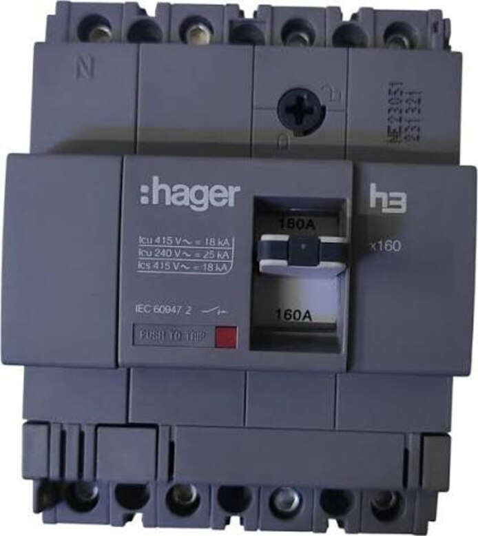
An MCCB nameplate ampere value does not tell you whether the breaker suits your system voltage, prospective fault current, cable, load or coordination plan. By the end, you will have a specification checklist covering interrupting capacity, trip settings, installation derating, application duty and the documents a dealer must provide.
Key takeaways
- Compare Icu and Ics with calculated fault current at the installation voltage.
- Confirm frame size, continuous current rating and trip-unit settings.
- Check pole configuration, frequency, terminals, enclosure and mounting limits.
- Request coordination tables, test certificates, datasheets and a complete offer.
Which voltage and short-circuit ratings apply at your installation?
Obtain the prospective short-circuit current at the MCCB terminals, not just the transformer nameplate fault level. Compare that calculated RMS value at the site’s actual voltage and 50 or 60 Hz frequency with the breaker’s Icu and Ics values at the same voltage.
IEC Icu and UL AIC are different labels and must not be treated as interchangeable.
Check the dealer’s selection against these points:
- Confirm the MCCB rated operational voltage Ue matches the system line-to-line voltage. Do not use rated insulation voltage Ui as a substitute; a breaker can have a high Ui but a lower interrupting rating at the selected Ue.
- Record the rated impulse withstand voltage Uimp for the installation’s surge and insulation-coordination requirements.
- Request Ics as well as Icu when the breaker must remain serviceable after a fault or interrupt repeated faults. Ics is stated as a percentage of Icu.
- Ask for rated short-circuit making capacity Icm when the breaker could close onto a fault or face a high prospective peak current.
- If selective coordination uses short-time delay, verify Icw, its duration, and the available short-time pickup and delay settings.
| Rating | What to compare | What can go wrong |
|---|---|---|
| Icu and Ics | Fault current at stated Ue and frequency | A high Icu can conceal a much lower service capacity |
| Ui and Uimp | Insulation and impulse withstand requirements | Insulation figures do not prove interruption performance |
| Altitude data | Above about 2,000 m | Insulation, thermal, and fault ratings can each require separate correction |
What frame, current and trip-unit ratings are actually being supplied?
A 400 A frame does not mean the feeder will receive 400 A protection. Confirm the MCCB frame size, then identify the trip-unit current and the settings applied to that trip unit.
The frame size is the breaker’s physical current platform and maximum compatible rating. Rated current In is the continuous current rating of the supplied trip unit or rating plug.
A 400 A frame fitted with a 250 A trip unit remains a 250 A device for continuous-duty selection; do not accept the frame label as In.
Ask the dealer to state these values on the quotation and product data sheet:
- MCCB frame size and its maximum frame rating.
- Rated current In of the installed trip unit or rating plug.
- Long-time pickup Ir and long-time delay range.
- Short-time and instantaneous trip settings, including their adjustment ranges.
- Ground-fault pickup and delay, where the protection study requires them.
Set Ir from the feeder design current, conductor ampacity and permitted overload, not from the frame rating. Confirm that the proposed short-time and instantaneous ranges match the study.
A short-time delay can support selective coordination only if the breaker’s rated short-time withstand current Icw and its duration support that delay; Icw is not the breaking capacity.
For a motor feeder, compare instantaneous or short-time pickup with starting current and coordinate the MCCB with the separate overload relay. A breaker’s short-circuit rating does not replace motor overload protection.
Will the MCCB match the system arrangement and installation limits?
An MCCB must match the circuit’s conductors, busbar layout, enclosure, and earthing arrangement—not just its ampere marking. Confirm the MCCB number of poles, the required pole-to-pole wiring, and whether the neutral needs switched neutral and neutral protection.
| Check | Confirm before purchase | Failure if mismatched |
|---|---|---|
| Poles and neutral | Number of poles; solid or switched neutral; neutral overcurrent protection | The breaker may leave the neutral connected during isolation or fail to protect an unbalanced neutral |
| Supply type | AC or DC, system voltage, frequency, polarity, and the manufacturer’s AC and DC MCCB ratings | An AC rating does not prove safe DC interruption; DC ratings can depend on polarity and poles connected in series |
| Cables and terminals | Conductor size, material, lug type, terminal capacity, and required tightening torque | A correctly rated breaker can overheat at an undersized terminal or poorly matched lug |
| Busbar and enclosure | Busbar dimensions, spacing, mounting orientation, ventilation, and the exact listed enclosure | Heat buildup, inadequate clearance, or incompatible connections can invalidate the rating |
| Temperature and altitude | Ambient temperature derating and altitude derating for the complete installation | At high temperature or above about 2,000 m, continuous current, insulation, and interruption performance can fall |
Ask for the table covering the intended enclosure and mounting arrangement. Confirm rated operational voltage Ue, not only insulation voltage Ui, and obtain the actual trip-unit In or Ir alongside the frame size.
If the feeder runs continuously, verify whether a 100%-rated breaker is required. That claim applies only to the listed breaker, enclosure, conductors, and terminals together; a larger frame alone does not create a 100%-rated installation.
Is the breaker suitable for the actual load and starting conditions?
A 125 A running load does not prove that a 125 A MCCB is suitable. Starting, energising, switching and fault conditions determine whether it trips unnecessarily or leaves equipment exposed.
- Motors: provide the motor starting current, starting time and starting method. Confirm the MCCB instantaneous or short-time pickup stays above that current, then verify coordination with the separate overload relay. The MCCB short-circuit rating does not replace motor overload protection.
- Transformers: state the transformer kVA, primary voltage and transformer inrush current. Ask for a setting that withstands energisation without allowing a winding fault to pass.
- Generators: check the generator’s available fault current, transient behaviour and neutral-earthing arrangement. Confirm generator protection and ground-fault protection will operate at the generator’s lower fault current.
- Capacitors: give the capacitor-bank size, switching arrangement and expected inrush. Confirm capacitor protection and MCCB settings will tolerate switching surges without nuisance trips.
- Welders: use maximum input current, duty cycle and phase loading, not the nameplate running average. A short, high welding pulse can trip a breaker sized only for average current.
- Ordinary feeders: compare calculated demand and continuous load with cable ampacity, while checking any downstream motor or transformer inrush.
Request time-current curves and a coordination study for the actual devices. Also ask whether Icm covers the peak making current and whether Ics and Icw, including its duration, suit repeated faults or short-time selectivity; these ratings are not interchangeable.
What coordination and supply documents should the dealer provide?
The dealer must provide a coordination study based on the actual upstream and downstream device models, ratings, trip settings and fault-current levels. A catalogue claim that two breakers are “selective” does not prove selective coordination across the full range.
Request these documents and confirmations:
- Time-current curves for every breaker, with long-time, short-time and instantaneous settings shown.
- A coordination study identifying the current range in which selectivity holds, plus clearing times and any overlap.
- The MCCB’s Icw short-time withstand current, duration and short-time pickup/delay settings. Icw is not the breaker’s ultimate breaking capacity.
- Icu, Ics and Icm values at the installation voltage. Icm is the peak making-current capacity, not the rms interrupting rating.
- A tested and permitted cascading or series-rated combination when the prospective fault current exceeds the individual MCCB rating.
- A signed order schedule listing poles, AC or DC system, polarity and pole wiring, trip-unit type, every setting and each accessory: auxiliary contacts, alarm contact, shunt trip, undervoltage release, motor operator and terminals.
| Evidence | What it proves | Reject it when |
|---|---|---|
| Coordination study | Device selectivity and clearing sequence | It uses substitute models or default settings |
| Manufacturer combination table | Tested cascading or series-rated protection | It lacks the certification basis or voltage |
| Approved bill of materials | Ordered hardware matches the design | Accessories or trip settings are unspecified |
For a motor feeder, confirm instantaneous or short-time pickup against starting current and coordination with the separate overload relay. Contact Electrical & Automation Pvt Ltd should identify these selections on the quotation, not leave them to site assembly.
Related product
 | LOW VOLTAGE POWER DISTRIBUTION PRODUCTS Moulded Case Circuit Breakers (MCCB) Moulded Case Circuit Breakers (MCCB) 3VA/3VM/3VJ - 16 AMP To 1600 AMP View product → |
Frequently asked questions
Which voltage and short-circuit ratings should you confirm for an MCCB?
Compare the calculated prospective RMS short-circuit current at the MCCB terminals with Icu and Ics at the installation voltage and 50 or 60 Hz frequency. Do not rely only on the transformer nameplate fault level.
What MCCB current details should the dealer identify?
Ask the dealer to state the frame rating, continuous current rating and trip-unit rating, along with the available long-time, short-time, instantaneous and earth-fault settings.
What installation details must match the MCCB?
Confirm pole count, system arrangement, neutral switching, frequency, terminal orientation, conductor size, mounting position, enclosure dimensions and the manufacturer’s temperature or altitude limits.
What documents should an MCCB dealer provide?
Request the exact datasheet, rating label information, type-test or test certificates, wiring and dimension drawings, trip settings, coordination tables and the supply model or part number.