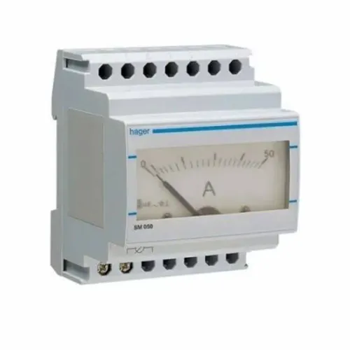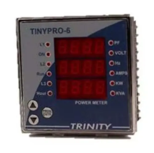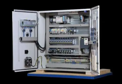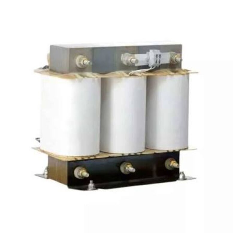
A variable-frequency drive, UPS or capacitor bank does not automatically mean you need a harmonic filter. You need to establish whether distortion is creating a system-level problem, where it occurs, how it compares with the point-of-common-coupling limits, and which corrective method fits the supply, load and operating pattern.
Key takeaways
- Measure voltage and current THD at the PCC and at suspected nonlinear loads.
- Compare individual harmonic orders and demand-based current limits with IEEE 519-2022.
- Use a filter when harmonic currents persist; choose other corrections for resonance or poor power factor.
- Give the supplier load data, one-line diagrams, analyser files, and operating conditions.
What harmonic distortion means—and which symptoms justify investigation
Harmonic distortion is waveform energy at frequencies above the 50 Hz or 60 Hz fundamental. Voltage THD measures the combined distortion of the supply-voltage waveform; current THD measures distortion in the load-current waveform. Individual harmonic orders identify specific components, such as the 3rd harmonic, 5th harmonic and 7th harmonic.
High current THD does not automatically mean high voltage THD: harmonic current creates voltage distortion only as it flows through source and distribution impedance.
| Measurement or symptom | What it indicates | Why investigate |
|---|---|---|
| Voltage THD | Distorted voltage at the bus or load | Can cause motor noise, drive instability, power-electronic equipment faults and excess losses |
| Current THD | Distorted current drawn by non-linear loads | Can produce transformer heating, nuisance trips and conductor losses |
| 3rd harmonic, 5th harmonic or 7th harmonic | A dominant individual order | The 5th and 7th commonly affect drives and motors; the 3rd increases neutral current |
| Triplen harmonics | The 3rd, 9th, 15th and other multiples of three | In a three-phase, four-wire system, they add in the neutral instead of cancelling, overheating the neutral conductor and transformer |
Likely sources include:
- Six-pulse variable-frequency drives, UPS systems, switched-mode power supplies, battery chargers, LED drivers, welding equipment and rectifiers.
A capacitor bank that fails, nuisance-trips, or worsens 5th- or 7th-harmonic voltage deserves investigation because resonance can amplify distortion. Engage a filter supplier after a measured or predicted consequence, such as overheating, repeated drive trips, motor torque pulsation or generator instability—not merely because a drive exists.
Which measurements reveal whether the problem is local or system-wide
A high current THD inside a drive panel does not prove a point of common coupling (PCC) violation. Harmonic voltage depends on harmonic current flowing through source and distribution impedance, so the same load can produce little distortion on a stiff utility service but severe distortion on a transformer-fed or generator-fed bus.
Collect the same power-quality analyser readings at each location:
- Phase-to-phase voltage, phase-to-neutral voltage, current, frequency, kW, kVA, power factor and kVAR.
- Voltage THD, current THD, each individual harmonic magnitude, and neutral current.
- Operating load, capture duration, demand interval, and whether values are maximum or average.
| Location | What to capture | What it reveals |
|---|---|---|
| Utility incomer or generator output | Voltage THD, current THD and spectra | Distortion entering from the supply or generator |
| Main bus | Voltage and current trends | System-wide propagation and bus impedance effects |
| Capacitor-bank feeder | Harmonic current during switching and operation | Resonance, capacitor stress or amplified 5th and 7th harmonics |
| Variable-frequency-drive feeder | Current THD and individual harmonic magnitude | A local nonlinear source |
| Affected load or internal panel | Local voltage, current and neutral current | Whether the symptom begins downstream |
If the internal panel has high current THD but the PCC voltage remains acceptable, investigate the local feeder before specifying a filter. Escalate a system-wide problem when voltage THD rises at the PCC, neutral or transformer heating persists, or capacitor and breaker operation changes with load.
Capture readings across a representative measurement interval, including normal demand and the highest expected operating load.
How to read the analyser report against IEEE 519-2022
Start at the point of common coupling (PCC), not at the panel with the largest percentage. For systems at or below 1 kV, the commonly cited IEEE 519-2022 voltage harmonic limits at the PCC are 5% maximum total harmonic voltage distortion and 3% for any individual harmonic.
These are system-performance targets, not universal limits for every internal bus.
1. Confirm the analyser location. A drive feeder can show severe current distortion while the utility incomer remains within PCC compliance. Record whether the report measures the utility or generator connection, main bus, or an internal feeder.
2. Separate current TDD from instantaneous THD. IEEE 519 current limits use total demand distortion, with maximum demand current as the fundamental-current denominator over the defined demand interval. A lightly loaded system can show high instantaneous THD while delivering less harmonic current than it does at full demand.
3. Calculate the PCC Isc/IL category. Isc is available short-circuit current; IL is maximum demand fundamental current. Common table categories allow 5% TDD at the lowest ratio, then 8%, 12%, 15%, and 20% as Isc/IL rises. A fixed 5% current-THD trigger is therefore wrong for every facility.
4. Compare voltage and current separately. Current THD alone cannot establish a voltage-distortion violation because voltage distortion depends on harmonic current flowing through source and distribution impedance. Escalate a reading when full-demand results, PCC voltage distortion, equipment symptoms, or repeated limit exceedances point to a system consequence.
When the cause points to a filter—and when another correction fits better
Match the remedy to the measured cause: a six-pulse drive with strong 5th and 7th current harmonics may need filtering, while poor power factor, voltage unbalance, loose connections or voltage sags need different corrections.
| Option | What it does | When it fits |
|---|---|---|
| Line reactor or DC-link choke | Reduces drive harmonic current; neither equals a full filter | Use at an individual six-pulse drive when moderate reduction is enough |
| 12-pulse converter with phase-shifting transformer | Uses phase cancellation to reduce characteristic 5th and 7th harmonics | Choose it for a suitable new installation; imbalance, incorrect phase displacement, mismatched bridges and changing operating conditions weaken cancellation |
| Detuned capacitor bank | Uses series reactors to move resonance below a selected harmonic | Improve power factor while limiting capacitor-bank resonance; it is not a tuned harmonic filter |
| Tuned filter | Provides a low-impedance path for specified harmonic orders | Use a passive harmonic filter when measured orders are stable and predictable |
| Active harmonic filter | Measures load current and injects compensating current across multiple orders | Use for changing harmonic loads; check compensation capacity, response time, installation impedance and cost |
Do not treat current THD as proof that a filter will solve voltage distortion. Harmonic voltage depends on source and distribution impedance, so a generator supply can distort more than a stiff utility service because its higher impedance amplifies the same current; check alternator heating, automatic-voltage-regulator behaviour and filter interaction.
Investigate transients, undersized conductors, loose terminations and voltage unbalance separately. A capacitor bank that resonates with the system needs switching and impedance analysis, not simply a larger filter. A generator-fed system needs its own assessment before transferring a utility-designed solution.
What a harmonic filter supplier needs before recommending equipment
Do not approve filter sizing from a drive nameplate or one analyser screenshot. A harmonic filter supplier needs the system architecture, operating conditions and measured consequences because harmonic voltage depends on source impedance, not current THD alone.
1. Provide the one-line diagram, transformer kVA, transformer impedance, utility or generator short-circuit level, voltage, grounding arrangement and intended point of common coupling (PCC). This supports a proper PCC assessment and prevents a filter from being sized for the wrong bus.
2. Identify every nonlinear load: drive ratings and pulse number, UPS units, rectifiers, welders, battery chargers, LED supplies and large switched-mode power supplies. Add the capacitor-bank rating, detuning reactor, step sizes, controller settings and switching arrangement; an unplanned resonance can damage capacitors or trip breakers.
3. Supply the load profile for minimum, normal and maximum operation, including kW, kVA, power factor, motor starts and generator operation. A generator harmonic assessment matters because higher source impedance can turn an acceptable utility reading into excessive voltage distortion.
4. Attach analyser records for phase-to-phase and phase-to-neutral voltage, current, frequency, kW, kVA, kVAR, voltage THD, current THD, individual harmonic orders and neutral current at the incomer, main bus, capacitor feeder, drive feeder and affected load. Record duration, demand interval and maximum versus average values.
A passive filter designed from one snapshot can detune or overload after a transformer change, generator connection, capacitor-bank modification or load expansion. Engage a supplier when those data show PCC risk, overheating, torque pulsation, drive trips, generator instability or breaker and capacitor operation—not merely because a drive exists.
Contact Electrical & Automation Pvt Ltd can be compared with other suppliers once the measurements support filter selection and low-voltage integration.
Related product
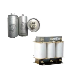 | LOW VOLTAGE POWER DISTRIBUTION PRODUCTS Capacitors, Harmonics Filters, Relays, Capacitor duty Contactors Capacitors, Harmonics Filters, Relays, Capacitor duty Contactors View product → |
Frequently asked questions
What symptoms justify investigating harmonic distortion?
Investigate overheating in transformers, neutral conductors, cables or capacitors; nuisance trips; equipment noise; failed capacitors; motor heating; and unexplained power-quality alarms.
Which measurements show whether harmonics are local or system-wide?
Measure voltage and current THD, individual harmonic orders, RMS current, load demand, and power factor at the point of common coupling and at suspected nonlinear loads.
How should you compare an analyser report with IEEE 519-2022?
Check voltage distortion and individual voltage harmonics at the point of common coupling, then compare current distortion with the short-circuit ratio, demand current, and applicable limits.
When is a harmonic filter the right correction?
A filter fits when identified harmonic currents require reduction and the installation has enough operating data for correct tuning, rating, and resonance checks.
What information does a harmonic filter supplier need?
Provide the single-line diagram, transformer rating and impedance, short-circuit data, load schedule, nonlinear-load details, analyser files, operating states, and capacitor-bank information.