A changeover switch must transfer the connected load safely under its actual voltage, fault level, load type, neutral arrangement, and operating sequence. By the end, you will have a supplier-checking framework that covers transfer behavior, sizing, standards evidence, installation limits, controls, maintenance, and the documents needed for a defensible selection.
Key takeaways
- Specify open, closed, or delayed transition before requesting quotations.
- Match current, poles, neutral switching, and load duty to the installation.
- Request type-test reports, routine-test records, and protection coordination data.
- Confirm bypass safety, site conditions, commissioning, and maintenance support.
Define the Transfer Arrangement Before Comparing Suppliers
A supplier cannot size the arrangement from “automatic transfer” alone. State whether the load needs open transition, closed transition, or delayed transition, then define which source transfers to which source and what interruption the equipment may tolerate.
| Option | Transfer behaviour | Application consequence |
|---|---|---|
| Open transition | Break-before-make; the first source disconnects before the second connects | Prevents intentional source paralleling but interrupts the load |
| Closed transition | Make-before-break; sources overlap briefly | Requires synchronism, voltage, frequency, phase-angle control, interlocking, and utility approval |
| Delayed transition | Disconnects the first source, waits in a neutral position, then connects the second | Suits residual-voltage decay or motor-load conditions but extends the interruption |
1. Identify the operating arrangement: a manual changeover switch needs an operator; a motorised changeover switch needs a motor drive and control circuit; automatic equipment needs sensing, source selection, and a defined failure response.
2. For utility-to-generator transfer, inverter changeover, or another automatic duty, request the actual undervoltage and overvoltage pickup/dropout, frequency limits, phase-loss and phase-sequence detection, engine-start delay, transfer delay, retransfer delay, cool-down time, and failure-to-transfer action.
3. If maintenance continuity matters, specify bypass-isolation equipment and demand its tested operating sequence. Confirm how the load remains energised while the transfer mechanism is withdrawn, and how source isolation is proved.
Require exercise-transfer intervals, contact and interlock inspections, control-battery checks, manual-operation provisions, and records for failed or incomplete transfers. These controls can fail while the power contacts remain healthy.
Size the Switch for Current, Load Duty, Poles, and Neutral Arrangement
Do not choose the switch from nameplate amperes alone. Calculate the continuous load current after applying the diversity factor, add known future capacity, then check derating for ambient temperature, enclosure, ventilation, conductor arrangement, and terminal temperature. Compare that result with the switch’s rated current, not merely its maximum frame size.
Ask the supplier to confirm the making, breaking, and thermal duty for:
- Transformer magnetizing current and inrush
- Motor starting current and motor duty
- Capacitor-bank inrush
- UPS input current and rectifier behaviour
- Harmonic-rich electronic loads
The steady current can look identical while the switching stress differs sharply. Require the stated utilization category: IEC 60947 AC-31 suits mainly resistive loads, AC-32 covers mixed resistive and inductive loads, and AC-33 covers motor loads or mixed loads containing motors. A resistive-duty switch is not automatically suitable for a motor-heavy board.
Select the pole arrangement from the source earthing and neutral-bonding design. A single-phase circuit usually requires switched line and neutral; a three-phase circuit may use three poles with a solid neutral or four poles with a switched neutral.
Use a switched neutral when the installation requires source separation or has separate generator and utility neutral bonds. Confirm that switching the neutral will not leave the load floating, interrupt protective-earth continuity, or create parallel neutral paths. Get the supplier to state the permitted neutral arrangement, pole sequence, and terminal rating.
Read the Datasheet and Request the Correct Test Evidence
A short-circuit certificate alone does not prove that a switch can perform repeated on-load transfers. Confirm the exact model, pole arrangement, Ue, Ie, fault withstand ratings, and utilization category shown on the datasheet.
| Evidence | What it proves | Reject if missing |
|---|---|---|
| IEC 60947-6-1 test certificate | The equipment was assessed as transfer-switching equipment | The supplier cites only a general switch standard |
| IEC 60947-3 certificate | Compliance as a switch, disconnector, switch-disconnector, or fuse-combination unit | It is presented as proof of transfer duty by itself |
| AC-31 or AC-32 rating | AC-31 covers mainly resistive loads; AC-32 covers mixed resistive and inductive loads | The category does not match your connected load |
| Electrical and mechanical endurance report | The device survived the stated number of load transfers and mechanical operations | Only a short-circuit test result is supplied |
| Bypass-isolation test record | The stated bypass sequence and withdrawn-transfer arrangement were tested | The supplier cannot identify source isolation and operating steps |
Ask for test reports that identify the complete assembly, including accessories, controls, interlocks, and neutral configuration. A successful fault-current test proves performance during that test; it does not prove routine transfer life.
For emergency-power installations, match the complete transfer assembly to NFPA 110 where that standard governs the project. Request documented evidence covering transfer timing, generator-start interfaces, bypass features, and periodic testing, not a certificate for the switch body alone.
Require a maintenance plan stating exercise-transfer intervals, contact and interlock inspections, auxiliary-supply checks, manual operation, and records for failed or incomplete transfers.
Check Automatic Controls, Bypass Safety, and Installation Conditions
Require the supplier to document the complete transfer sequence, not merely label the unit “automatic.” State whether the application needs open transition, closed transition, or delayed transition, then record source-priority logic, undervoltage and overvoltage thresholds, frequency limits, start delay, transfer delay, retransfer delay, cooldown time, manual controls, test mode, and load-shed or inhibit inputs.
| Transition | Operating result | Control evidence required |
|---|---|---|
| Open transition | Break-before-make; the load loses power briefly | Transfer and retransfer delays, source acceptance thresholds, and interruption time |
| Closed transition | Sources overlap briefly; intentional paralleling occurs | Voltage, frequency, phase-angle synchronism, interlocking, paralleling duration, and utility approval |
| Delayed transition | Both sources disconnect before the second connects | Neutral or residual-voltage delay, discharge time for motors and transformers, and reconnection limits |
If maintenance continuity matters, demand a tested bypass-isolation configuration and its permitted operating sequence. Confirm how the mechanism is isolated, how the load is transferred to bypass, how source isolation is proved, and whether bypass operation remains protected during a fault. A bypass handle alone proves none of these points.
Ask for installation limits covering ambient temperature, altitude, humidity, pollution level, enclosure rating, ventilation, mounting orientation, conductor arrangement, cable-bending space, terminal-temperature limits, and clearances. Request the prospective fault current and the applicable SCCR, conditional rating, Icw, or Icm.
For North American equipment, verify the marked UL 1008 rating and its required fuse class, breaker frame, upstream device, and maximum fault current. Check the complete assembly against NFPA 110 when emergency-power rules apply.
Make the Supplier Prove Commissioning, Maintenance, and Application Fit
Before awarding the order, require a commissioning pack that proves the proposed assembly works in your installation, not just in a laboratory. It must identify the transfer mode, source interlocks, generator-start interface, sensing settings, control supply, neutral switching, bypass sequence, and acceptance-test results.
1. Request operating-life evidence. Electrical endurance must match the load and utilization category; mechanical endurance must state the operation count and test conditions. A short-circuit certificate proves fault performance, not survival through years of routine transfers.
2. Require a documented test and maintenance plan covering exercise-transfer intervals, contact and interlock inspection, control-battery or auxiliary-supply checks, manual-operation provisions, and records of failed or incomplete transfers. Test automatic sensing and generator-start signals; a healthy power circuit does not prove healthy controls.
3. If maintenance continuity matters, demand evidence that the proposed bypass-isolation arrangement is a tested configuration. Obtain the permitted switching sequence and confirm how it achieves load continuity, source isolation, phase alignment, and safe operation during faults.
4. Make the supplier state whether the assembly is open, closed, or delayed transition. For closed transition, require synchronism, voltage, frequency, phase-angle, interlocking, and utility-approval provisions. For emergency systems, check the complete assembly against NFPA 110, including transfer timing, generator controls, bypass features, and testing.
Contact Electrical & Automation Pvt Ltd should map the selected equipment to your load schedule and provide these commissioning records before its catalogue category is treated as application proof.
Related product
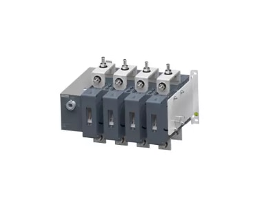 | LOW VOLTAGE POWER DISTRIBUTION PRODUCTS On load Changeover Switches View product → |
Frequently asked questions
What transfer arrangement should you define before comparing suppliers?
State whether the system needs open transition, closed transition, or delayed transition, identify both sources, and specify the interruption the load can tolerate.
Which ratings must you check on an on-load changeover switch?
Check rated operational current, utilization category, short-circuit withstand, number of poles, neutral switching, source voltage, frequency, and the load duty.
What test evidence should you request from a supplier?
Request the switch datasheet, type-test report, routine-test records, short-circuit withstand evidence, and control-panel test results that match the quoted configuration.
What installation and support details should a supplier prove?
Confirm enclosure conditions, ambient temperature, cable entry, bypass interlocking, control logic, commissioning steps, maintenance intervals, spare parts, and application responsibility.