A capacitor bank sized from an advertised kVAR range can deliver too little correction at your operating voltage or create overheating and resonance in a harmonic-rich network. By the end, you will have a practical checklist for sizing the bank, testing the installation conditions, comparing protection and control details, and evaluating a supplier’s complete technical offer.
Key takeaways
- Size kVAR from measured kW, existing power factor and target power factor.
- Select capacitor voltage after checking harmonics, switching frequency and operating conditions.
- Demand self-healing dielectric protection, discharge resistors and defined end-of-life failure controls.
- Compare controller logic, capacitor switching hardware, panel safety and replacement support.
Size the Bank From Measured Load and Delivered kVAR
Calculate the required capacitor-bank kVAR from measured kW, existing power factor and target power factor:
Qc = measured kW × [tan(cos⁻¹ existing power factor) − tan(cos⁻¹ target power factor)]
For example, raising 1,000 kW from 0.80 to 0.95 requires about 421 kVAR before allowing for load variation, capacitor tolerance and future expansion. APFC capacitor sizing based only on the transformer rating or an advertised bank range can leave the plant under-corrected or drive it into a leading power factor.
Confirm the quoted output at the plant’s actual voltage and frequency. Capacitor kVAR changes approximately with the square of voltage, so a capacitor rated 50 kVAR at 440 V delivers only about 41.3 kVAR at 400 V, before reactor losses.
Ask the supplier to state separately:
- Capacitor-only kVAR, net delivered kVAR and voltage used for the calculation
- Net output at the measured operating voltage, rated frequency and each switching step
- Harmonic-current limit at the capacitor terminals, maximum permissible RMS current and assumed harmonic spectrum
- IEC 60831-1 and IEC 60831-2 performance basis, including the 1.10-times voltage and 1.3-times current limits
With a 7% detuned reactor, a nominal 100 kVAR capacitor stage delivers roughly 93 kVAR at fundamental frequency before other losses. Require measured harmonic data, transformer impedance and operating states of drives, UPS systems, rectifiers and welders before accepting that design.
Match the Capacitor Voltage to Harmonic and Switching Conditions
A 440 V capacitor is suitable on a 400–415 V system when voltage distortion is low, switching is moderate, and the measured bus voltage remains within the capacitor’s rating.
Confirm the supplier’s maximum RMS capacitor current, harmonic-current limit, thermal duty and assumed harmonic spectrum; a satisfactory fundamental power factor does not prove that capacitor current is safe.
Check net kVAR at the actual voltage and frequency. A 50 kVAR capacitor rated at 440 V produces only about 41.3 kVAR at 400 V, before reactor effects. A 7% detuned reactor also reduces fundamental output to roughly 93% of the capacitor-only rating, so require both capacitor kVAR and net delivered kVAR.
Before choosing the voltage rating, give the supplier:
- Measured voltage THD and current THD at the capacitor connection point
- Harmonic current by order, transformer impedance and utility short-circuit level
- Operating states for drives, UPS systems, rectifiers, welders and existing capacitors
- Switching frequency, step size and expected inrush conditions
| Option | Specify it when | Critical check |
|---|---|---|
| 440 V capacitor | Clean 400–415 V bus and conventional switching | Confirm RMS current and temperature limits |
| 480 V capacitor bank | Harmonic or switching stress exceeds a 440 V design’s margin | Recalculate delivered kVAR at system voltage |
| 525 V capacitor bank | Severe harmonic voltage, reactor-related voltage rise or high thermal stress | Do not assume the higher rating solves resonance |
| Detuned reactor | Capacitors could resonate near a significant harmonic | Demand a resonance study and net-kVAR figure |
| Tuned filter or active harmonic filter | Specific harmonic currents require reduction | Select tuning or filtering from measured spectra, not nonlinear-load percentage alone |
Use capacitor-duty contactors with pre-insertion resistors; rapidly changing loads can justify thyristor switching, with its added heat and protection requirements.
Check Dielectric Construction, Ratings and End-of-Life Protection
Specify a self-healing dielectric, not merely “heavy-duty” construction. Self-healing limits damage after a local dielectric breakdown, but repeated clearing raises loss and temperature. The specification must name the pressure-sensitive disconnector or equivalent internal failure isolation, individual or group fusing, and the visible or electrical failure indication method.
| Specification | Require the supplier to state | Why it matters |
|---|---|---|
| IEC 60831-1 and IEC 60831-2 | Rated voltage, capacitance tolerance, 1.10 times rated voltage for up to 8 hours in 24 hours, and continuous current limit of 1.3 times rated current | Confirms performance beyond nominal kVAR |
| Thermal duty | Ambient category, including -40/D limits of 55 °C maximum and 45 °C 24-hour average, ventilation, altitude derating, and kVAR derating | Reactor and enclosure heat can push capacitor temperature above room temperature |
| Harmonic duty | Maximum capacitor-terminal RMS current, assumed harmonic spectrum, and reactor heat-loss basis | Acceptable site voltage THD does not guarantee acceptable capacitor current |
| Discharge | Residual voltage of 75 V or less within 3 minutes, test points, and a delay or interlock preventing reconnection before discharge | A charged capacitor can injure personnel and fail during rapid cycling |
| Assembly protection | IEC 61439 conditional short-circuit rating, peak withstand, protective-device type and rating, and coordination assumptions | A can fuse does not establish the APFC panel’s short-circuit rating |
Ask for maintenance access to capacitor terminals or a defined test point. A failed element left energised behind only an upstream bank fuse can continue overheating before isolation.
Verify Switching, Controller Logic and Panel-Level Safety
A switching stage needs a capacitor-duty contactor, not an ordinary motor contactor. Ask for the inrush-limiting method, such as pre-insertion resistors, because uncontrolled energisation can weld contacts. Rapid load changes may justify a thyristor-switched APFC, but the design must account for semiconductor heat, bypass protection and service access.
Require the supplier to document these points:
- Show the CT location and polarity on the single-line diagram. The CT should measure the incoming current for the loads and capacitor bank, with its polarity marked toward the source. Specify the response to a lost, reversed or incorrectly wired CT signal.
- Show each stage’s kVAR, minimum switching interval, reconnection delay and switching sequence. Leading-power-factor prevention must include a leading-power-factor lockout or reverse-kVAR logic; otherwise a lightly loaded shift can become capacitive even when full-load correction is accurate.
- State switching endurance as operations, not only capacitor life in hours. Include the assumed operations, replacement intervals and spares for contactors, precharge resistors, controller relays, reactor insulation, cooling fans and fuse holders. Confirm stage-level isolation for maintenance.
- Request capacitor-terminal RMS-current and thermal limits, plus the assumed harmonic spectrum. Site voltage THD and fundamental power factor alone cannot prove safe capacitor duty.
For the complete enclosure, request the IEC 61439 short-circuit withstand or conditional short-circuit rating, peak withstand, protective-device type and rating, and coordination assumptions. A capacitor can’s internal fuse rating does not establish the assembly’s short-circuit capability.
Compare Technologies and the Supplier’s Complete Life-Cycle Offer
A capacitor’s stated life in hours does not reveal the cost of keeping an APFC bank running. Compare the dielectric, failure mode, replacement work and complete assembly support.
| Option | Maintenance and service life | Spares and ownership cost |
|---|---|---|
| Cylindrical aluminium capacitor | Compact and straightforward to replace, but heat, overcurrent and repeated switching accelerate ageing. Check terminal temperature, pressure-disconnector operation and the supplier’s assumed switching operations. | Lower unit cost is useful only if matching cans, fuses and terminals remain available. A short replacement interval can outweigh the purchase saving. |
| Metallised polypropylene dry-type capacitor | Self-healing dielectric construction limits many small faults and avoids liquid leakage. It still needs protection from excessive RMS current, harmonic heating and high ambient temperature. | Usually simplifies housekeeping, but compare replacement-can cost, discharge components and end-of-life isolation. Ask for measured thermal limits, not only a life-hours figure. |
| Oil-filled capacitor | Liquid impregnation can support insulation performance, but leakage, sealing and disposal create additional maintenance concerns. Inspect the enclosure and request the failure-containment arrangement. | Include leak response, removal, transport and disposal in the total cost. Confirm that replacement units and compatible protection remain available. |
| Complete bank assembly | The panel adds contactors, precharge resistors, reactors, relays, fans, fuse holders and a controller, each with its own wear pattern. | Demand stage isolation, spare-part numbers, replacement intervals and switching-endurance assumptions, plus the assembly’s IEC 61439 short-circuit rating and coordination data. |
During an APFC supplier evaluation, ask for net kVAR at your operating voltage, capacitor-terminal RMS-current and harmonic-spectrum limits, and a five-year spares schedule. Contact Electrical & Automation Pvt Ltd can be assessed against those documents rather than against capacitor-can price alone.
Related products
 | Aluminium Yashcap Capacitor KVAR RATING:- 1KVAR TO 33.1 KVAR, RATED VOLTAGE:- 440V, 3PHASE, Usage/Application:- Capacitor Panel, Material:- Aluminium, Application:- Industrial... View product → |
 | ACCUVAR POWER FACTOR CONTROLLER ACCUVAR POWER FACTOR CONTROLLER Accuvar Steps: 8 TO 16, THREE CT Type - LCD Display, Size: 144x144x55 mm Mounting Type: Panel Mounting View product → |
Frequently asked questions
How do you size an APFC capacitor bank?
Calculate required kVAR from measured load, existing power factor and target power factor, then select practical capacitor steps for the load profile.
What capacitor voltage rating is suitable for an APFC panel?
Match the capacitor voltage to the system voltage and account for harmonic amplification, switching conditions and expected operating stress.
Which capacitor construction and protection features should you verify?
Check the dielectric construction, rated temperature and voltage, self-healing behaviour, discharge resistors and end-of-life pressure-disconnection protection.
What should you check in APFC switching and controller logic?
Verify step sizing, switching sequence, reconnection delay, controller response to changing load, contactor or thyristor selection and panel-level safety.
How should APFC capacitor suppliers be compared?
Compare capacitor and switching technologies alongside commissioning, harmonic assessment, documentation, spares, maintenance and end-of-life support.
Related products
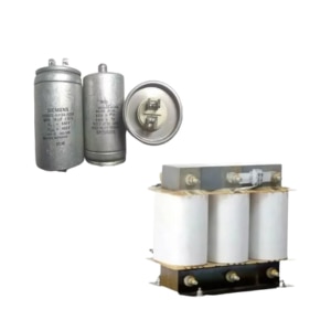 | LOW VOLTAGE POWER DISTRIBUTION PRODUCTS Capacitors, Harmonics Filters, Relays, Capacitor duty Contactors Capacitors, Harmonics Filters, Relays, Capacitor duty Contactors View product → |
 | APFCR RELAY SINGLE CT Number Of Steps : 6 to16 Steps, Mounting Type: Panel Mounting, Single CT Type - LCD Display, size: 144x144x55 mm. View product → |