An HRC fuse base does more than hold a fuse: it maintains the contact path, contains accessible live parts, and helps the fuse operate safely during a fault. By the end, you will be able to distinguish the base’s rating from the fuse-link’s protection duty, match the assembly to its installation, and check coordination before energising it.
Key takeaways
- Match voltage, current, breaking capacity, fuse class, and terminal ratings.
- Size the fuse for load current, cable capacity, inrush, and coordination.
- Inspect contact pressure, temperature rise, enclosure clearance, and mounting torque.
- Confirm markings, isolation, continuity, and phase identification before energising.
What happens inside an HRC fuse base during a fault?
The base does not clear the fault; the HRC fuse-link does. The HRC fuse base function is to hold the fuse securely and maintain a low-resistance electrical contact path through its fuse holder, terminals, and mounting structure. Before a fault, it keeps the current path stable and positions the fuse correctly.
1. Before interruption, spring-loaded contacts and correctly tightened terminals carry the continuous current without excessive heating. The base must match the fuse-link’s size, contact arrangement, poles, voltage, AC or DC duty, and mounting method.
2. During a short circuit, the current-limiting fuse element melts rapidly. The fuse-link limits peak let-through current, then its filler material helps extinguish the arc inside the sealed body. The base contains the link, maintains contact, and withstands the resulting thermal and electrodynamic forces; its ampere rating is not the fuse-link’s breaking capacity.
3. After interruption, the base keeps live parts shielded and provides a secure position for isolation, inspection, and replacement. Do not treat the carrier as a load-break switch unless its design specifically permits that use.
A blown-fuse indicator or auxiliary microswitch only reports status. It does not increase interrupting capacity or make the fuse holder safe to remove while energized. Use the fuse-link’s interrupting rating for the prospective fault current, and verify the base’s complete electrical duty separately.
Which ratings and markings must match?
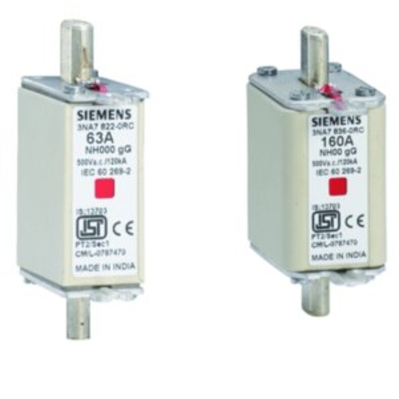
A 100 A fuse-link and a 100 A fuse base do not have the same job. The fuse-link’s fuse rated current, time-current curve, breaking capacity, and peak let-through current come from the link; the fuse-base rating describes the holder’s continuous current, contact system, temperature rise, and mechanical duty.
A base’s ampere marking is not its short-circuit interrupting rating.
| Marking | Identifies | Do not confuse it with |
|---|---|---|
| Fuse-link | Current rating, class, rated voltage, and breaking capacity | The fuse-base rating |
| Fuse base | Permitted fuse size, contact arrangement, poles, rated voltage, and continuous current | The link’s interrupting capability |
| Complete assembly | Tested short-circuit duty under stated conditions | Any link of the same nominal current |
Check every marking and datasheet before installation:
- Match the fuse-link dimensions, knife contacts or cylindrical contacts, pole count, carrier orientation, and mounting method to the base. A link that fits physically can still make poor contact or leave inadequate creepage and clearance.
- Match rated voltage, frequency, utilization category, and AC and DC application. Do not infer a DC rating from an equivalent AC voltage; DC arcs lack the natural current zero that assists interruption.
- Confirm the base manufacturer permits that exact fuse-link construction and provides its heat or derating data. Equal current ratings do not guarantee equal power dissipation.
- Verify the stated assembly short-circuit rating, including the specified fuse-link, conductors, upstream device, and installation arrangement. A replacement link can invalidate tested performance.
- Treat indicator contacts and auxiliary microswitches as signalling devices only; they do not increase breaking capacity or permit load switching.
How do you size the fuse and coordinate the protection system?
Choose the fuse-link from the continuous load, then verify that it survives the circuit’s normal inrush without allowing the cable to overheat. A fuse sized only for running current can open during motor starting current, transformer inrush, or capacitor inrush; one oversized to avoid nuisance operation can leave the cable and equipment inadequately protected.
Check these values in order:
- Set the fuse-link’s continuous current rating below the cable’s corrected ampacity and above the expected steady load. Apply ambient-temperature, enclosure, grouping, and installation derating.
- Compare the fuse time-current curve with the actual starting or energising profile. An aM fuse is for motor short-circuit protection and requires a separate overload relay; it does not provide overload, phase-loss, or contactor coordination. A gG fuse provides full-range protection.
- Confirm the prospective short-circuit current at the installation does not exceed the fuse-link’s rated breaking capacity. Use the available fault current, not the transformer’s nameplate current alone.
- Prove selectivity against upstream and downstream devices using manufacturer time-current curves, pre-arcing and total clearing I²t data, and selectivity tables for the stated fault-current range. A smaller downstream fuse alone does not prove discrimination.
- Select the base for the complete duty: fuse-link dimensions and contacts, continuous current, rated voltage, frequency, utilization category, AC or DC service, and prospective fault current. DC requires specific ratings because it has no natural current zero.
The base must also appear on the manufacturer’s permitted fuse-link list. Equal ampere markings do not guarantee equal heat dissipation, and the base’s current rating is not its interrupting capacity.
How do fuse class, heat, and installation affect reliability?
Choose the fuse class for the fault it must clear, not only for the circuit’s ampere rating.
| Class | Protection role | When it applies |
|---|---|---|
| gG fuse | Full-range general-purpose protection | Feeders, cables, and distribution circuits where overload and short-circuit protection are both required |
| aM motor protection | Partial-range short-circuit protection | Motor circuits, paired with a correctly coordinated overload relay; it does not replace overload, phase-loss, or contactor protection |
| aR semiconductor protection | Partial-range, very fast semiconductor protection | Drives, rectifiers, and power-electronic devices where low let-through energy matters |
| gR fuse | Full-range semiconductor protection | Semiconductor circuits needing overload and short-circuit interruption across the fuse’s specified range |
Heat and installation errors can defeat a correctly selected link. Tighten terminals to the manufacturer’s torque, use the specified conductor cross-section, and keep adjacent devices within the stated spacing. Loose joints create resistance heating; crowded bases trap heat and raise contact temperature.
Check these details before energising:
- Mount the carrier or base only in its permitted orientation, with ventilation and clearances shown in its instructions.
- Keep fuse exhaust paths and hot surfaces away from cable insulation, barriers, and neighbouring equipment.
- Fit the specified fuse-link and carrier combination; another link with the same ampere rating can invalidate the tested short-circuit rating.
- Preserve shrouds, barriers, and finger-safe covers so live contacts remain inaccessible.
- Do not remove a fixed fuse holder while current flows. Use a load-break switch-fuse or switch-disconnector-fuse with the required utilization category for operational switching.
For DC service, verify a DC-rated assembly: an equivalent AC voltage does not provide the same arc-interruption duty.
What should a purchase and commissioning check include?
Before installing or replacing an HRC fuse-base assembly, obtain the exact manufacturer part number, fuse system, datasheet, installation instructions, and coordination records. “Same ampere rating” is not enough: short-circuit performance can depend on the specified fuse-link, upstream device, conductors, and mounting arrangement.
| Evidence | Obtain | Check |
|---|---|---|
| Standards and identity | IEC 60269-1, IEC 60269-2, fuse-link and base part numbers | Confirm the fuse system, dimensions, poles, voltage, and AC or DC duty |
| Thermal installation | Permitted fuse-link list, derating data, terminal range, torque values | Confirm the chosen link’s heat dissipation is approved for that base |
| Fault duty | Test conditions or certification for the assembly’s short-circuit rating | Match the stated rating to the specified link, upstream device, and conductor layout |
| Coordination | Time-current curves, pre-arcing and total clearing I²t, prospective fault current, and selectivity tables | Verify selectivity across the actual fault-current range, not from fuse size alone |
- Inspect contacts, barriers, shrouds, clips, and insulation for damage, looseness, tracking, or missing touch protection.
- Check conductor size, stripping length, bending space, phase identification, and enclosure clearance against the instructions.
- Torque each terminal to the manufacturer’s value; record it. Overtightening can strip threads, while low torque creates heat.
- After energising, record load current and inspect for abnormal temperature rise or voltage drop.
When obtaining a quote from Contact Electrical & Automation Pvt Ltd, provide these records and the existing fuse markings so the proposed assembly is checked against the tested configuration rather than matched by amperage alone.
Related products
 | LOW VOLTAGE POWER DISTRIBUTION PRODUCTS HRC Fuses & Fuse base 2 amp to 1000 amp View product → |
 | LOW VOLTAGE POWER DISTRIBUTION PRODUCTS Fuses for Semiconductor Protection Fuses for Semiconductor Protection 20 amp to 1000 amp View product → |
Frequently asked questions
What happens inside an HRC fuse base during a fault?
The HRC fuse-link melts and limits the fault current; the base holds it securely and preserves a low-resistance contact path.
Which ratings and markings must match on an HRC fuse base?
Match the fuse-link voltage, current, breaking capacity, class, physical size, terminal rating, and the base’s marked specifications.
How do you size the fuse and coordinate the protection system?
Select a fuse above the normal load current but below the cable’s allowable current, then check starting current, overload protection, and upstream-downstream discrimination.
How do fuse class, heat, and installation affect reliability?
Fuse class determines the protection duty, while heat, loose contacts, poor ventilation, incorrect torque, and inadequate clearances increase failure risk.
What should a purchase and commissioning check include?
Verify markings, documentation, compatibility, condition, mounting, torque, phase identification, continuity, insulation, and safe operation before energising.
Related product
 | Miniature Circuit Breaker 10kA, 1P (MCB) Miniature Circuit Breaker 10kA, 1P (MCB) Current RATING:- 10kA, 1P, 6A TO 63AMP, Brand:- Hager, Product Category:- 1P MCB, C-CURVE. View product → |