A panel ammeter does not measure amperes directly at its display terminals: a shunt or current transformer first converts conductor current into a measurable electrical signal. By the end, you will be able to identify the sensing method, match a meter to its CT and waveform, wire it safely, commission it, and recognise when another instrument is the better choice.
Key takeaways
- A CT measures high current indirectly; a shunt measures voltage across known resistance.
- Confirm whether the displayed value is RMS, average-responding, or peak-derived.
- Never open-circuit a live CT secondary or exceed the meter’s input rating.
- Specify current range, accuracy, input method, display, and system frequency before buying.
From conductor current to a digital ampere reading
An ammeter does not read the conductor directly. Its sensing element converts current into a small electrical signal: a current transformer (CT) produces a proportional secondary current, while a shunt produces a small voltage drop across a calibrated resistance.
The input circuit conditions that signal, an analogue-to-digital converter samples it, and the processor calculates the value shown in amperes.
For AC, the single phase digital ammeter working principle usually means calculating RMS current from many samples, not displaying the instantaneous current at one moment. A sine wave rated at 10 A RMS reaches about 14.1 A at its peak.
Switching power supplies and variable-speed drives can distort the waveform, so a meter’s true-RMS performance matters; an averaging meter can show the wrong value.
Route only the phase conductor through the CT or clamp. If phase and neutral pass through the same CT, their opposing magnetic fields cancel and the reading approaches zero.
The meter then applies its configured scale: a 200/5 A CT produces 5 A secondary current at 200 A primary current, so entering 100/5 instead gives a stable but incorrect result.
The display is trustworthy only when the CT ratio, polarity, burden, wiring length, frequency and input limits match the installation. A conventional iron-core CT measures AC, not steady DC; a DC-capable design needs a shunt or dedicated electronic sensor. An ammeter also measures current only—it does not calculate power without voltage and phase-angle information.
CT, shunt, direct input or clamp: where the current is sensed
Put the sensor around or in series with the phase conductor, not around the complete phase-and-neutral cable. A current transformer (CT) sees the alternating magnetic field from that one conductor; passing phase and neutral through the same CT makes their opposing fields cancel and the reading approach zero.
What a single phase ammeter uses depends on its input architecture:
| Method | How current is sensed | Correct placement |
|---|---|---|
| CT input | An external CT produces a lower secondary current; the meter applies the programmed ratio | Pass the phase conductor through the CT window and wire its secondary to the meter |
| Direct shunt input | A low-value resistor creates a small millivolt signal in series with the load | Insert the shunt in series with the phase conductor; never connect a high-current feeder directly to a 5 A CT input |
| Clamp sensor | A hinged CT or Hall-effect sensor detects the field without opening the circuit | Clamp around one conductor only, with the jaws fully closed |
A 200/5 A CT delivers 5 A to the meter when its primary carries 200 A. Set the meter to 200/5; the wrong ratio produces a stable but proportionally false value. Match the CT’s secondary rating, burden, class and polarity as well.
A conventional iron-core CT measures AC, not steady DC. A DC-capable single phase ammeter uses a shunt, Hall-effect sensor or another specified transducer. A CT-only ammeter also measures current, not power, because power measurement needs voltage and phase-angle information.
What the displayed AC value means—and what the rating hides
A display of 37.4 A normally represents RMS current, the heating-equivalent value of the AC waveform, not its instantaneous peak. That is how a single phase for digital ammeter measures current: it samples a conditioned shunt or CT signal, calculates a value, and refreshes the screen.
A sine wave gives predictable results; a phase-angle controller, inverter or switched-mode supply can make an averaging meter read low unless it uses true-RMS processing within its stated crest-factor and frequency range.
Check these limits before trusting the number:
- CT ratio: A 200/5 A CT delivers 5 A at 200 A primary current. Program the wrong ratio and the reading can remain stable while being proportionally wrong.
- CT conditions: Specify secondary rating, class, burden and polarity together. Long leads, loose terminals, excess connected instruments and CT saturation create ratio error or a falsely low reading.
- Accuracy: “0.5%” is incomplete without knowing whether it means percentage of reading, full scale, or both. Temperature, frequency, conductor position and waveform distortion affect the whole chain.
- Resolution: One decimal place does not prove one-decimal accuracy. A 0.1 A display step can sit beside an error larger than 0.1 A.
- Overload: Compare continuous and short-duration input ratings. Exceeding a direct shunt input can damage it; excessive primary current can saturate a CT and hide the fault.
A CT-only ammeter cannot calculate real power or energy because it has no voltage or phase-angle measurement. Verify the indicated value against a calibrated reference at the actual load and waveform.
Safe installation, commissioning and fault-finding
A blank display does not prove the measured circuit is de-energised. Isolate and lock out the feeder, then prove your voltage tester on a known live source, test the feeder, and prove the tester again. The ammeter’s auxiliary supply can be dead while the measured conductor remains live.
- Match the wiring diagram to the instrument: direct-input terminals accept only their marked current range; CT inputs require the stated secondary rating, such as 5 A or 1 A.
- Pass only the phase conductor through the CT. Do not pass phase and neutral together, because their magnetic fields cancel and the display approaches zero.
- Connect CT polarity correctly, keep secondary leads short, and close the CT secondary shorting link before disconnecting an energized CT circuit. An open CT secondary can produce dangerous voltage.
- Set the exact CT ratio, such as 200/5 A, then energize the circuit and compare the display with a correctly rated clamp meter.
If the display remains blank, check auxiliary supply voltage, control fuses, terminal tightness, and the meter’s input configuration before blaming the current circuit. If it reads zero, confirm that the load is running and that the sensor surrounds the phase conductor rather than a cable pair.
A steady but incorrect value points to the wrong CT ratio, reversed or misplaced sensing, excessive CT lead burden, or a loose connection. A fluctuating value can result from a changing load, distorted waveform, or a connection fault. Never use the ammeter as overcurrent protection; install separate protective and trip equipment.
When this meter is the right instrument—and how to specify one
Choose a single-phase digital ammeter when you need a clear current value from one conductor for panel indication, load checking, or alarm decisions—not energy consumption or power calculation.
| Option | What it measures | Choose it when |
|---|---|---|
| Single-phase digital ammeter | Current in one phase conductor | You need a continuous panel reading and have a suitable direct input, shunt, or CT |
| Clamp meter | Current through a conductor without opening the circuit | You need commissioning, temporary checks, or fault-finding at several locations |
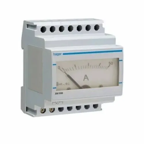
| Moving-iron ammeter | Current through an electromechanical movement | You need a rugged, simple indication and accept lower resolution and slower response |
| Energy meter | Voltage, current, power, power factor, and accumulated kWh | You need billing, consumption records, or energy reporting |
| VAF or multifunction meter | Voltage, amperage, frequency, and sometimes additional parameters | You need several panel readings in one instrument |
| Earth-leakage relay | Residual current from phase and neutral imbalance | You need leakage protection or an alarm, not ordinary load-current indication |
Before buying, compare the input type, nominal current or CT ratio, CT secondary rating, burden, accuracy class, frequency range, True-RMS capability, auxiliary supply, display range, overload rating, terminal safety category, panel cutout, ingress protection, and conformity documentation.
A 200/5 A CT needs a meter configured for 200/5 A; the wrong ratio gives a stable but wrong result.
Ask a digital ammeter supplier in Nagpur to state those values on the quotation. Contact Electrical & Automation Pvt Ltd can help you separate the measurement input from the auxiliary supply when specifying a panel instrument.
Related product
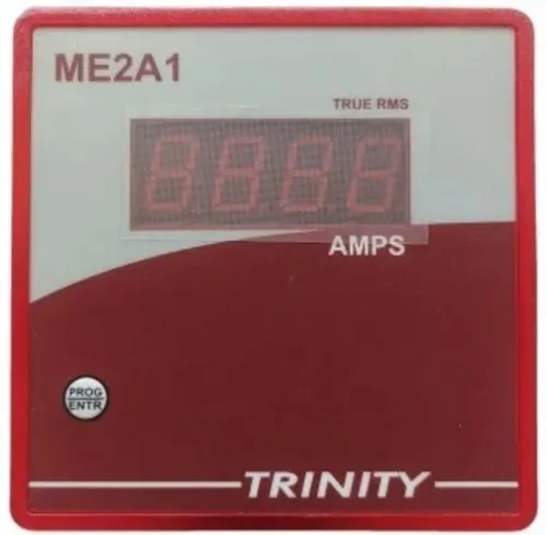
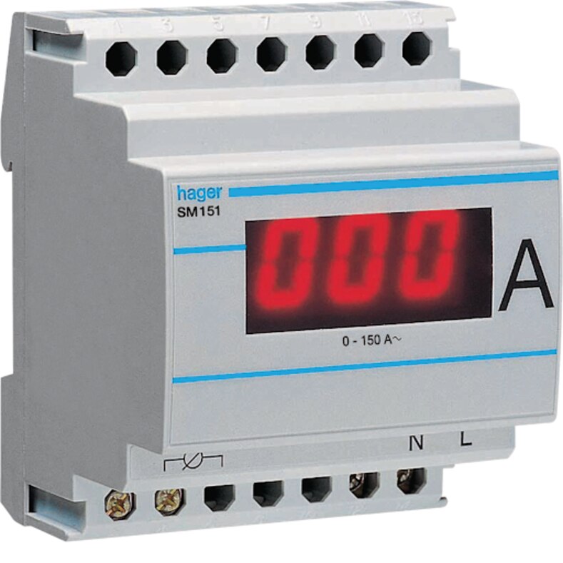
 | SINGLE PHASE AMMETER (ME2A1) AMPS (0-5000A AC) Of One phase on 0.56" seven segment LED View product → |
Frequently asked questions
How does a single-phase digital ammeter measure current?
It converts sensed current into a low-level electrical signal, then conditions and digitises that signal for the display. A current transformer produces a proportional secondary current, while a shunt produces a calibrated voltage drop.
Where does a digital ammeter sense current?
The sensing point can be a current transformer, shunt, direct current input, or clamp. Select the method based on conductor current, insulation and isolation requirements, available panel space, and installation access.
What does the AC value on a digital ammeter mean?
The displayed value represents the meter’s measurement method, such as true RMS, average-responding, or a peak-derived calculation. Check the datasheet before using the reading on distorted waveforms or nonlinear loads.
How do you install and troubleshoot a single-phase digital ammeter safely?
Isolate and prove dead before wiring the meter, match CT polarity and ratio, tighten terminals, and verify the configured range. For a CT installation, never leave the secondary open while the primary is energised; investigate zero, unstable, or excessive readings by checking wiring, configuration, sensing method, and load current.
Keywords