A relay supplier must prove more than a model number and a list of protection functions. By the end, you will be able to match relay capabilities to your asset, challenge CT and communication claims, verify standards and test evidence, and compare suppliers on performance that survives commissioning and fault investigation.
Key takeaways
- Match relay functions to the asset and fault you need to clear.
- Verify CT ratios, wiring, burden, curves, and inputs before comparing prices.
- Demand relay test reports, injection results, and a witnessed acceptance procedure.
- Confirm communications, event records, settings control, and long-term technical support.
Match protection functions to the asset and the failure you need to clear
Select the relay by the failure it must clear, not by its input count. Transformer protection needs differential or restricted-earth-fault functions alongside 50/51 overcurrent and 50N/51N earth fault; feeder protection usually needs phase and earth-fault curves, while voltage or frequency functions serve system conditions.
| Asset | Functions to match | Device fit and wrong choice |
|---|---|---|
| Transformer | Differential, 50/51, 50N/51N, 27, 59, 81 | Numerical transformer relay; a basic overload relay cannot detect internal winding faults |
| Incomer | 50/51, 50N/51N, 27, 59, 81 | Numerical protection relay with breaker-failure logic; an electronic overload relay is not incomer protection |
| Feeder | 50/51, 50N/51N, 27, 59 | Numerical feeder relay; an earth-leakage relay alone misses phase-to-phase faults |
| Motor | 49, 46, locked-rotor, phase-loss, earth fault | Motor-management relay; an electronic overload relay suits simpler starters, but not detailed motor management |
| Capacitor bank | 50/51, 50N/51N, 27, 59, unbalance and overcurrent | Dedicated capacitor-bank relay; a motor-protection circuit breaker is the wrong choice for bank unbalance |
| Generator | 50/51, 50N/51N, 27, 59, 81, 46, reverse power | Numerical generator relay; feeder-only protection leaves loss-of-field and negative-sequence risks |
For motors, compare pickup ranges, thermal models, cold and hot curves, restart behavior, RTD inputs, and coordination with the starter or variable-frequency drive. Use 27 for under-voltage, 59 for overvoltage, 81 for frequency protection, 46 for negative-sequence, and 49 for thermal protection.
An earth-leakage relay needs the correct residual-current sensor; it does not replace 50N/51N protection.
Check the inputs, curves, and CT installation before comparing relay prices
A relay that passes a nominal pickup test can still misoperate in service. Start with the installed CT and VT data, then test the complete protection chain against the highest fault current, asymmetry, coordination margin, and breaker operating time.
1. Record the CT ratio, CT class, knee-point voltage, winding resistance, lead resistance, and total secondary burden. Check CT saturation and remanence under the maximum asymmetrical fault current. Confirm CT polarity, CT grounding, and residual-current wiring; errors here can create false differential or earth-fault current.
2. Match the relay input to the circuit: verify its rated secondary current, VT input rating, frequency range, voltage burden, pickup range, and withstand ratings. Calculate the actual secondary burden, including leads, meters, transducers, and relay inputs. An overloaded CT or incorrect VT connection invalidates the relay accuracy claim.
3. Plot the relay’s time-current curves with upstream and downstream devices at minimum and maximum fault current. Include setting tolerances, reset characteristics, breaker time, trip output capacity, and operating-time tolerance. A single laboratory trip-time figure cannot prove coordination near a grading margin.
4. Request accuracy and timing data across the intended current, voltage, frequency, temperature, auxiliary-supply, and burden ranges. Test secondary injection at key points, then verify binary inputs and outputs, trip-circuit supervision, breaker-failure logic, and the actual breaker trip path.
If the supplier cannot provide these calculations and curves using your CT, VT, and fault-study values, compare engineering evidence—not relay prices.
Demand test evidence instead of accepting an ‘IEC compliant’ claim
Treat “IEC compliant” as an incomplete answer. Ask the supplier to identify the exact editions and scope of IEC 60255-1, IEC 60255-26 EMC, IEC 60255-27 product safety, and IEC 60255-151 overcurrent protection that apply to the relay and its declared functions.
Request the following before approval:
- A type-test report covering EMC, insulation, surge, vibration, temperature range, and auxiliary-supply variation for the specified model and hardware revision.
- A routine-test report for the offered serial number, including wiring, insulation, functional operation, and calibration checks.
- Secondary injection results showing pickup, reset, operating-time tolerances, and metering accuracy across the proposed current, voltage, frequency, and burden ranges.
- A calibration sheet stating current accuracy, voltage accuracy, frequency accuracy, and power and energy accuracy; reject a sheet that gives only nominal pickup.
- A witnessed checklist covering binary I/O checks, trip and close circuit supervision, loss-of-auxiliary-supply behavior, breaker-failure logic, disturbance-record retrieval, and representative interlocking tests.
| Evidence | What it proves | Approval check |
|---|---|---|
| Type-test report | Design withstand and environmental suitability | Model and hardware revision match |
| Routine-test report | Factory condition of the supplied relay | Serial number matches the offer |
| Secondary-injection record | Protection and measurement performance | Values stay within declared tolerances |
A relay that passes pickup alone has not proved that it will operate the intended breaker. Ask for output-contact operating times and logic diagrams, then compare them with coordination margins.
Evaluate communications, records, settings control, and long-term support
A relay that speaks Ethernet is not automatically interoperable with your automation system. For IEC 61850, request an independent IEC 61850 conformance-test report stating the IEC 61850 edition and profile, Logical Nodes, GOOSE messaging, sampled values, and supported SCL files. For Modbus RTU over RS-485, obtain the register map, exception behaviour, scaling, and gateway limitations.
- For event records and oscillography, require the sampling rate, trigger logic, pre-trigger storage, recording duration, channel scaling, file format, and traceable time synchronisation. Verify whether SNTP, PTP, or IRIG-B meets the accuracy required for trip sequence-of-events or sampled-value analysis during network loss and failover.
- Require a settings management workflow with controlled setting files, version identification, an audit trail, role-based access, offline validation, and proof of which settings were active when the relay tripped.
- Make cybersecurity cover the relay, engineering software, maintenance laptop, gateways, and network. Ask for firmware support periods, defect notifications, patch procedures, backup and restore, rollback capability, revalidation requirements, replacement-unit availability, software-licence continuity, and environmental suitability.
Ask Contact Electrical & Automation Pvt Ltd to supply this evidence pack rather than a feature brochure. Reject a proposal that cannot show how engineers will retrieve readable records, recover an approved configuration, identify a firmware mismatch, and diagnose a communication failure years after commissioning.
A protocol name proves compatibility only when the tested data model, timing performance, files, and maintenance process are documented.
Related product
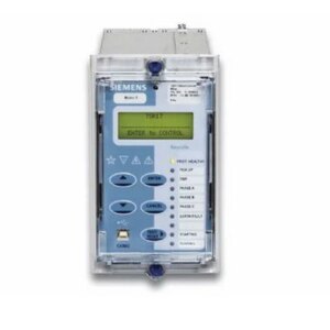 | LOW VOLTAGE POWER DISTRIBUTION PRODUCTS Numerical Relays View product → |
Convert the supplier comparison into a witnessed acceptance and handover plan
Score final offers against witnessed evidence, not the lowest relay price or pickup figure. Use a supplier scorecard that assigns pass/fail status to the complete protection path, from instrument inputs through the breaker trip circuit, interlocking, records, and future maintenance.
| Comparison point | Evidence to demand | Acceptance decision |
|---|---|---|
| Relay and wiring | Secondary-injection test, binary I/O checks, trip and close circuit supervision | Reject if pickup passes but the breaker trip circuit does not operate |
| Automation | Communications verification, time synchronisation, disturbance-record retrieval | Accept only when alarms, records, and timestamps are correct |
| Interlocking | End-to-end interlocking test covering network congestion, switch failure, VLAN configuration, and loss of supervision | Require measured transfer times and defined fail-safe actions |
| Auxiliary supply | Loss-of-auxiliary-supply test showing relay, alarm, and trip behavior | Record recovery time and every unexplained indication |
| Configuration | Controlled setting files, version identification, change audit trail, backup and restore | Keep the approved file with the handover record |
| Lifecycle | Maintenance training, firmware support, and replacement availability | Price support gaps before selecting the offer |
- Witness each test with signed results, test equipment identification, injected values, trip times, and the final active settings.
- Retrieve a disturbance record after a simulated trip and prove that it identifies the active setting version.
- Demonstrate loss of supervision at the relay and control-system displays; do not accept a silent failure.
- Obtain as-built drawings, access credentials, test scripts, training records, and restoration media at handover.
Frequently asked questions
How do you match a numerical relay to the protected asset?
Select functions according to the failure you need to clear. Transformer protection can require differential or restricted-earth-fault protection with 50/51 overcurrent and 50N/51N earth-fault functions. Feeder protection usually requires phase and earth-fault curves, while voltage and frequency functions address system conditions.
What should you check before comparing numerical relay prices?
Check the required inputs and outputs, CT ratios, CT class, burden, polarity, wiring, protection curves, pickup values, time settings, and available communication interfaces. A lower-priced relay is not comparable if it lacks the required functions or installation compatibility.
What test evidence should a numerical relay supplier provide?
Ask for the relay model and firmware identification, factory test records, protection-function test results, binary input and output checks, communication tests, and secondary-injection results. Witness the agreed tests against approved settings before acceptance.
Which communications and records matter in a numerical relay?
Confirm the required protocol, such as Modbus RTU, Modbus TCP, IEC 61850, or IEC 60870-5-103, along with time synchronisation, event logs, fault records, oscillography, disturbance files, password control, and settings-change history.
How should relay acceptance and handover be managed?
Use an approved settings file, inspection checklist, secondary-injection test plan, communication test, trip-circuit verification, and witnessed acceptance record. Request final drawings, configuration files, test results, manuals, firmware details, passwords, and training at handover.