“Single CT” describes the relay’s measurement method, not proof that a current transformer is included in the carton. By the end, you will know which relay, CT, wiring, protection, switching hardware, and technical details belong in the quotation before you approve a single-CT APFC installation.
Key takeaways
- Confirm the CT ratio and install it on the incomer before downstream loads split.
- Match CT polarity, phase reference and secondary wiring to the relay terminals.
- Ask whether the quotation includes the CT, voltage leads, fuses and commissioning.
- Check step control, switching delay, alarm outputs and capacitor compatibility—not just step count.
What “single CT” means and what the quotation may include
A single-CT APFC relay has one external current-transformer input. The CT measures current in one phase, while the relay uses its voltage-sensing reference to calculate power factor and switch capacitor steps. This arrangement suits a reasonably balanced three-phase installation.
The name indicates one CT input, not one CT supplied as standard. These single ct apfc relay details must appear in the quotation:
| Relay-only quotation | Complete arrangement |
|---|---|
| Relay with CT input and output contacts | Relay, external CT, secondary wiring, voltage connections, auxiliary supply, and step-control hardware |
| CT, fuses, contactors, capacitors, and enclosure may be excluded | CT, CT shorting or test block, control fuses, capacitor-duty contactors, capacitors, discharge resistors, enclosure, terminals, and wiring are listed |
| Outputs intended to operate another switching device | Contactors or thyristor modules selected for the capacitor bank |
Confirm these connection groups before ordering:
- CT secondary input, including the relay’s 1 A or 5 A rating
- Voltage-sensing terminals
- Auxiliary supply terminals
- Capacitor-step output contacts
Do not assume the relay outputs carry capacitor current directly. Confirm whether they drive capacitor-duty contactors or another switching device.
Demand a line-by-line packing list marking every item as included or excluded. Ask specifically about the CT, CT shorting or test block, control fuses, contactors, capacitors, discharge resistors, enclosure, terminals, and internal wiring; a relay-only quote can omit all of them.
How to choose the CT ratio and position it on the incomer
Select the external CT from the maximum current the incomer will carry, not from the capacitor-bank kvar or transformer nameplate alone. A transformer can feed a load far below its rating, while an undersized CT can saturate or exceed its thermal and dynamic withstand ratings.
Your APFC relay single CT specifications should state:
- Primary current, 1 A or 5 A secondary, accuracy class, rated burden in VA, insulation level, frequency, window or bar form, thermal withstand, and dynamic withstand
- A CT secondary that matches the relay input exactly; do not connect a 5 A CT to a relay configured for 1 A
- A ratio close enough to preserve measurement resolution at the plant’s light load
| CT choice | Result | Correct action |
|---|---|---|
| Oversized primary | Poor light-load resolution and delayed or erratic step decisions | Select near the maximum incomer current |
| Undersized primary | Saturation, inaccurate power factor, or exceeded withstand ratings | Increase the ratio and verify fault-duty ratings |
Install the CT on the incomer between the utility source and the complete plant bus, so it measures aggregate load current. The relay must use that reference without counting capacitor current as load current. A feeder location sees only part of the demand; a capacitor-bank conductor measures the wrong current.
Either position can cause wrong power factor, overcompensation, undercompensation, or unstable switching. Use this as a single CT relay buying guide: confirm the CT position on the drawing before ordering.
CT polarity, voltage sensing, and safe secondary wiring
Before connection, obtain a manufacturer’s wiring diagram for the exact relay. The available product copy does not establish the terminal schedule, so do not guess from terminal labels. The diagram must identify the CT phase, relay voltage terminals, auxiliary supply, and whether voltage sensing is line-to-line or line-to-neutral.
1. Confirm CT orientation: place P1 toward the source and P2 toward the load. On the secondary, connect S1 and S2 according to the marked polarity; reversing them can make the relay read a leading load as lagging, or switch capacitor steps incorrectly.
2. Match the voltage reference to the CT phase. If the CT is installed on phase L1, the relay’s voltage reference must use the specified L1 relationship, whether the relay measures line-to-line or line-to-neutral voltage. The correct phase relationship lets it calculate the true power-factor angle.
3. Install a suitable CT shorting and test terminal block. Never open a CT secondary while primary current flows. Short S1-S2 before disconnecting the relay or test instrument, and verify secondary polarity before energisation.
4. Confirm the single-CT APFC relay details, including auxiliary and voltage-sensing control fuses or MCBs. Set their ratings against the relay manual and the panel design, not by copying an assumed terminal schedule.
Record these points in the approved connection drawing and inspection sheet. The drawing becomes the reference for commissioning, fault-finding, and future relay replacement.
What the relay must control beyond its number of steps
A relay with eight outputs is not necessarily suitable for an eight-step bank. Check the apfc relay single ct specifications for output quantity, capacitor-duty contact rating, minimum and maximum step size, fixed or rotating sequence, automatic switching, target power-factor setpoint, switching delay, reconnection delay, and capacitor discharge-delay protection.
Without discharge delay, a capacitor can reconnect while its voltage remains high, producing damaging inrush current.
A large first step makes a lightly loaded installation jump from lagging to leading power factor and back again. Smaller initial steps improve stability. Relay outputs normally operate capacitor-duty contactors or thyristor modules; they do not carry capacitor current directly.
Require undervoltage and overvoltage blocking, CT polarity or phase-error alarms, and displayed voltage, current, power factor, kvar, active steps, and alarm status.
The bank design also needs HRC protection, discharge resistors, correctly rated busbars and cables, and detuned reactors where drives, UPS units, rectifiers, welders, or other nonlinear loads create harmonic risk.
| Arrangement | Best fit | Limitation |
|---|---|---|
| Single CT | Broadly balanced three-phase load | Does not reveal phase imbalance |
| Three CTs | Materially unequal phase loading or phase-specific control | More wiring and measurement inputs |
Choose three-CT measurement for substantial phase-specific conditions. A single CT does not replace an energy meter or power-quality analyser. Ask a single ct apfc relay supplier to state every rating, switching limit, alarm function, and accessory in writing.
How to request a complete single-CT quotation in Nagpur
Send the supplier a site sheet, not only the words “single CT.” Include:
1. LV system voltage and frequency; maximum incomer current; transformer rating, impedance and secondary voltage; incomer-breaker frame and trip rating; proposed CT location; expected phase-load balance; capacitor-bank kvar; smallest and largest required steps; harmonic-producing loads such as drives, UPS systems, rectifiers and welders; ambient temperature, installation altitude and enclosure conditions; and utility or consultant requirements.
2. Ask the quote to mark each item included or excluded: relay, external CT, CT shorting or test block, voltage and auxiliary fuses, capacitor-duty contactors or thyristor modules, capacitors, discharge resistors, detuned reactor, enclosure, terminal hardware, internal wiring, programming, testing and commissioning.
3. Require the document to state the CT ratio, 1 A or 5 A secondary rating, accuracy class, burden in VA, insulation level, frequency, relay input setting, terminal diagram and output-contact rating. Confirm whether outputs drive contactors or thyristor modules, rather than capacitor current directly.
This checklist prevents an “apfc relay supplier single ct” quotation from being mistaken for a complete APFC panel. A relay with single-CT input and a complete panel are different purchase scopes.
For comparing apfc relay supplier single ct inclusions in nagpur, evaluate Contact Electrical & Automation Pvt Ltd against this documented scope, not the phrase “single CT” alone. Use this as your single ct relay buying guide.
Related products
 | APFCR RELAY SINGLE CT Number Of Steps : 6 to16 Steps, Mounting Type: Panel Mounting, Single CT Type - LCD Display, size: 144x144x55 mm. View product → |
 | APFC RELAY (NEWTON+8) Single CT Type- LCD Display, Size - 96x96 mm View product → |
Frequently asked questions
What does a single-CT APFC relay quotation include?
Request the relay, external current transformer, voltage-sensing connections, CT shorting or test terminals, control wiring, protection details and commissioning scope. Confirm whether the capacitor panel and installation are included separately.
How do you choose the CT ratio and position it on the incomer?
Choose a ratio that covers the maximum incomer current without excessive oversizing, such as 400/5 A for an incomer designed around 400 A. Mount the CT where it measures the complete installation load, upstream of outgoing feeders and capacitor connections.
How should you check CT polarity and secondary wiring?
Keep P1 toward the utility or transformer and P2 toward the loads, then connect S1 and S2 to the relay terminals shown in its wiring diagram. Never open an energised CT secondary; short it through a test link before removing the relay connection.
What should you check beyond the APFC relay’s number of steps?
Check the operating voltage, CT input rating, voltage-sensing phase, switching delay, reconnection delay, step sequence, alarm contacts, over- and under-voltage protection, and compatibility with the capacitor contactors or thyristor modules.
Related products
 | MOTORS CONTROL PRODUCTS Power Contactor, Control Contactor View product → |
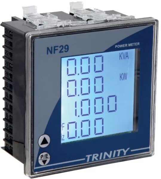 | MULTIFUCTION PANEL METER MODEL: NF29 MULTIFUCTION PANEL METER MODEL: NF29 MFM With Customized LCD, With THD View product → |
 | MOTORS CONTROL PRODUCTS Thermal Overload Relays, Motor Protection Circuit Breakers View product → |
 | ACCUVAR POWER FACTOR CONTROLLER ACCUVAR POWER FACTOR CONTROLLER Accuvar Steps: 8 TO 16, THREE CT Type - LCD Display, Size: 144x144x55 mm Mounting Type: Panel Mounting View product → |
Keywords